Difference between revisions of "Exercise STM Nucleo FCU English"
Wiki.admin (talk | contribs) |
Wiki.admin (talk | contribs) |
||
| Line 2: | Line 2: | ||
You will find on this page all informations, exercises and files you need to get started for making a FCU (Flight Control Unit) prototype during your lab work in class. | You will find on this page all informations, exercises and files you need to get started for making a FCU (Flight Control Unit) prototype during your lab work in class. | ||
| + | |||
| + | |||
| + | On this page, you will find all the information, exercises, and files necessary for getting started with and creating a prototype of an FCU (Flight Control Unit) as part of classroom-directed exercises (TD). | ||
| + | |||
| + | <h3><b>Basic Nucleo Functions</b></h3> | ||
| + | Void HAL_GPI0_Init(): This function is used for initializing input or output pins for LEDs or buttons available on the Nucleo board. | ||
| + | |||
| + | Void HAL_UART_Init(): This function is used for initializing the UART module (serial communication), which is used to communicate with the computer. | ||
| + | |||
| + | Void HAL_TIM_Base_Start(): This function is used to start a timer, useful for periodically updating a display or a sensor reading, for instance. | ||
| + | |||
| + | Void HAL_GPI0_ReadPin/WritePin(): This function is used to read or write the status of a port on the Nucleo board. | ||
| + | |||
| + | ==Installing STM Nucleo Libraries in the Arduino Software== | ||
| + | |||
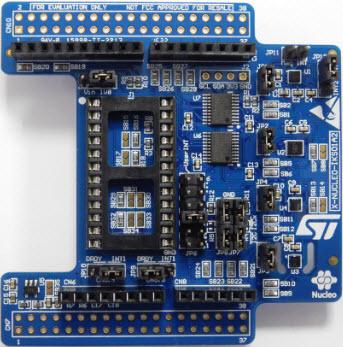
| + | [[File:carte_nucleo.jpg|400px|thumb|center|Nucleo board used]] | ||
| + | |||
| + | The X-Nucleo IKS01A2 board functions in the same way as an Arduino board; in fact, we use the same software (Arduino) to operate it and gather data. | ||
| + | |||
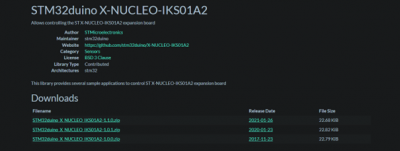
| + | To control this board via the Arduino software, it's necessary to install a library accessible via this link: https://www.arduinolibraries.info/libraries/stm32duino-x-nucleo-iks01-a2 | ||
| + | |||
| + | [[File:site_stm32.png|400px|thumb|center]] | ||
| + | |||
| + | Download the latest available version. A .zip file will be downloaded to your computer. | ||
| + | |||
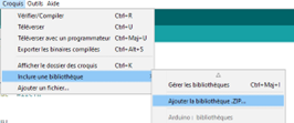
| + | In Arduino, go to Sketch -> Include Library -> Add .ZIP Library. | ||
| + | |||
| + | Select the previously downloaded file (do not unzip it). | ||
| + | |||
| + | [[File:installation1.png|thumb|center]] | ||
| + | |||
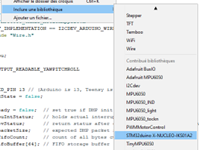
| + | To include this library in your code, go to Sketch -> Include Library -> STM32duino-X-NUCLEO-IKS01A2; the line of code #include <X-NUCLEO-IKS01A2.h> should appear. | ||
| + | |||
| + | [[File:installation_2.png|thumb|center]] | ||
| + | |||
| + | Now install the communication protocol used for the Nucleo board. For this, go to File -> Preferences, then enter this URL into the Additional Board Manager URLs: https://github.com/stm32duino/BoardManagerFiles/raw/main/package_stmicroelectronics_index.json | ||
| + | |||
| + | Click OK afterward. | ||
| + | |||
| + | [[File:installation3.png|thumb|center]] | ||
| + | |||
| + | The protocol is now downloaded; to install it, go to Tools -> Board Type -> Board Manager. | ||
| + | |||
| + | In the search bar, type "stm," you should see the following screen: | ||
| + | |||
| + | [[File:installation4.png|thumb|center]] | ||
| + | |||
| + | Select the latest available version (here 2.4.0) and click Install. The process takes a few minutes. If everything went well, the term INSTALLED should appear. | ||
| + | |||
| + | ==Exercise 1: Make an LED Blink== | ||
| + | |||
| + | <h3><b>Step 1: Connections</b></h3> | ||
| + | Connect an LED to a GPIO pin (for example, pin PA5) on the Nucleo board using a current-limiting resistor (for example, a 220-ohm resistor) in series with the LED. The positive terminal of the LED should be connected to the GPIO pin, and the negative terminal should be connected to the resistor and then to the ground (GND) of the board. | ||
| + | |||
| + | <h3><b>Step 2: Initialization</b></h3> | ||
| + | It's important to start with an IDE (Integrated Development Environment) that's compatible with the STM32 microcontroller. Create a new project for the Nucleo board by selecting the type of microcontroller used on your board (here STM32). | ||
| + | |||
| + | Add a source file "main.c" to your project. Add the header file for the microcontroller used in the Nucleo board (for example, stm32fxxx.h). These are the HAL library headers. | ||
| + | |||
| + | [[File:exercice1_1.png|thumb|center]] | ||
| + | |||
| + | Initialize the GPIO pin for output by writing a 1 in the appropriate configuration register (for example, GPIOA->MODER |= GPIO_MODER_MODE5_0). | ||
| + | |||
| + | <h3><b>Step 3: Code</b></h3> | ||
| + | Loop indefinitely and turn on the LED by writing a 1 in the output register (for example, GPIOA->BSRR = GPIO_BSRR_BS5) for a short period, then turn off the LED by writing a 1 in the output register (for example, GPIOA->BSRR = GPIO_BSRR_BR5) for another short period. Repeat this sequence to make the LED blink. | ||
| + | |||
| + | Here's an example C code that uses the Nucleo STM32F401RE board to make an LED connected to pin PA5 blink. | ||
| + | |||
| + | [[File:exercice1_2.png|thumb|center]] | ||
| + | |||
| + | <font color = "blue">Note: </font>The codes here use pin PA5 for the LED output; of course, you need to adapt to the pin you are connected to. This code uses the "for" function to wait for a short period after each state change of the LED. The number of loops can be adjusted to change the blinking speed of the LED. | ||
| + | |||
| + | <font color = "blue">Help: </font>Here is a typical wiring diagram for an LED on a Nucleo board. | ||
| + | |||
| + | [[File:exercice1_3.png|thumb|center]] | ||
| + | |||
| + | In this diagram, R1 is the current-limiting resistor, and GPIO is the GPIO pin on the Nucleo board to which the LED is connected. The positive terminal of the LED is connected to the GPIO pin, and the negative terminal is connected to the resistor, then to the ground (GND) of the board. | ||
| + | |||
| + | Note that the value of resistor R1 depends on the supply voltage of your Nucleo board and the characteristics of the LED you are using. A typical value for the resistor is 220 ohms. | ||
| + | |||
| + | |||
| + | |||
| + | ==Exercise 2: Retrieve the Position of a Non-Analog Joystick== | ||
| + | |||
| + | <h3><b>Step 1: Wiring</b></h3> | ||
| + | Plug the joystick into the Nucleo board using jumper cables. The joystick usually has two axes of movement (X and Y) and a pressure button. Each axis is connected to two pins (for example, pin A0 and pin A1), while the button is connected to another pin (for example, pin D2). Make sure to connect the joystick's correct pins to the corresponding pins on the Nucleo board. | ||
| + | |||
| + | <h3><b>Step 2: Initialization</b></h3> | ||
| + | Open your IDE and create a new project; then add a "main.c" source file. Next, include the header to use the HAL functions as in the previous exercise. | ||
| + | In the "main.c" function, initialize the GPIO reading pins by writing a 0 in the appropriate configuration register (for example, GPIOA->MODER &= ~(GPIO_MODER_MODE0_Msk | GPIO_MODER_MODE1_Msk)). | ||
| + | |||
| + | <h3><b>Step 3: Code</b></h3> | ||
| + | Loop indefinitely and read the corresponding GPIO pins to get the joystick's position. For this, you can use the "GPIO_ReadPin" function to read the GPIO pin value. Then, you can use conditions to determine the joystick's position (for example, if the X pin's value is low and the Y pin's value is high, the joystick is in the top right corner). | ||
| + | |||
| + | Here's a C language code example that uses the Nucleo STM32F401RE board to retrieve a non-analog joystick position connected to pins PA0, PA1, and PB2. | ||
| + | |||
| + | [[File:exercise2_1.png|400px|thumb|center]] | ||
| + | [[File:exercise2_2.png|400px|thumb|center]] | ||
| + | |||
| + | <font color = "blue">Note: </font>This example uses PC0 and PC1 pins for joystick inputs; you'll, of course, have to adapt to the pins you're using. | ||
| + | |||
| + | <font color = "blue">Hint: </font>Here is a typical wiring diagram to retrieve the non-analog position of a joystick on a Nucleo board. | ||
| + | |||
| + | [[File:exercise2_3.png|400px|thumb|center]] | ||
| + | |||
| + | <font color = "blue">Note: </font>In this diagram, R1, R2, and R3 are pull-down resistors, which set a reference state for each joystick pin. The joystick pins are connected to the Nucleo board using jumper cables. The X-Axis and Y-Axis pins are connected to two GPIO pins on the Nucleo board (for example, pins PA0 and PA1), while the Button pin is connected to another GPIO pin on the board (for example, pin PB2). The resistors R1, R2, and R3 are connected between each joystick pin and the board's ground (GND). | ||
| + | |||
| + | Note that the value of each resistor depends on the joystick and the Nucleo board you're using. A typical value for each resistor is 10k ohms. | ||
| + | |||
| + | ==Exercise 3: Control a Motor== | ||
| + | |||
| + | Plug your joystick using the board's analog pins, then create a new project in your IDE. | ||
| + | |||
| + | Next, add the following code to initialize the input analog pins connected to the joystick. | ||
| + | |||
| + | [[File:exercise3_1.png|400px|thumb|center]] | ||
| + | |||
| + | Create a function to read the joystick's analog values with the following code. | ||
| + | |||
| + | [[File:exercise3_2.png|400px|thumb|center]] | ||
| + | |||
| + | Use the coordinate values to control the motors with the following code. | ||
| + | |||
| + | [[File:exercise3_3.png|400px|thumb|center]] | ||
| + | |||
| + | In the main program (loop), call the functions created earlier. | ||
| + | |||
| + | [[File:exercise3_4.png|400px|thumb|center]] | ||
| + | |||
| + | Once compiled and uploaded to the board, the joystick movements will control the motors in the desired directions with precision due to analog operation (more forceful movement will cause more motor movement). | ||
| + | |||
| + | These simple exercises correspond to the functions that could be useful for basic use of the Nucleo board. | ||
| + | |||
| + | ==Exercise 4: Retrieve the Position of a Potentiometer== | ||
| + | |||
| + | For the final exercise, we thought of a very practical application for the Mini-Bee: it is about the Nucleo board's management of a potentiometer. Indeed, a drone must be able to ascend or descend vertically, implying a simultaneous increase or decrease in all rotors' speed. Thus, an analog potentiometer would allow for fine control of the device on the vertical axis. | ||
| + | |||
| + | To operate a potentiometer with a Nucleo board, here are the steps to follow: | ||
| + | |||
| + | First, you need to plug the potentiometer into a GPIO port on the board (which you should not forget to initialize, of course). Next, connect several LEDs to other GPIO pins, without forgetting to also plug in series protection resistors. These LEDs will serve to give a visual indication of the potentiometer's level of depression: the higher the analog signal emitted by the potentiometer, the more LEDs will light up. | ||
| + | |||
| + | Here is an example code that would allow you to retrieve the analog position of a potentiometer and display it using 3 LEDs. | ||
| + | |||
| + | #include"mbed.h" | ||
| + | |||
| + | AnalogIn enfoncement_potentiometre(A0); | ||
| + | |||
| + | DigitalOut led_1(D2); | ||
| + | DigitalOut led_2(D3); | ||
| + | DigitalOut led_3(D4); | ||
| + | |||
| + | int main() { | ||
| + | while(1) { | ||
| + | uint16_t valeur = enfoncement_potentiometre.read_u16(); | ||
| + | if (valeur < 50) { | ||
| + | led_1 = 0; | ||
| + | led_2 = 0; | ||
| + | led_3 = 0; | ||
| + | } | ||
| + | else if ((valeur >= 50) && (valeur < 2000)) { | ||
| + | led_1 = 1; | ||
| + | led_2 = 0; | ||
| + | led_3 = 0; | ||
| + | } | ||
| + | else if ((valeur >= 2000) && (valeur < 4000)) { | ||
| + | led_1 = 1; | ||
| + | led_2 = 1; | ||
| + | led_3 = 0; | ||
| + | } | ||
| + | else if (valeur >= 4000) { | ||
| + | led_1 = 1; | ||
| + | led_2 = 1; | ||
| + | led_3 = 1; | ||
| + | } | ||
| + | } | ||
| + | } | ||
Latest revision as of 11:58, 29 September 2023
Cette page est disponible en français sur le lien suivant : https://wiki.collaborativebee.com//index.php?title=Exercice_STM_Nucleo_FCU
You will find on this page all informations, exercises and files you need to get started for making a FCU (Flight Control Unit) prototype during your lab work in class.
On this page, you will find all the information, exercises, and files necessary for getting started with and creating a prototype of an FCU (Flight Control Unit) as part of classroom-directed exercises (TD).
Basic Nucleo Functions
Void HAL_GPI0_Init(): This function is used for initializing input or output pins for LEDs or buttons available on the Nucleo board.
Void HAL_UART_Init(): This function is used for initializing the UART module (serial communication), which is used to communicate with the computer.
Void HAL_TIM_Base_Start(): This function is used to start a timer, useful for periodically updating a display or a sensor reading, for instance.
Void HAL_GPI0_ReadPin/WritePin(): This function is used to read or write the status of a port on the Nucleo board.
Installing STM Nucleo Libraries in the Arduino Software
The X-Nucleo IKS01A2 board functions in the same way as an Arduino board; in fact, we use the same software (Arduino) to operate it and gather data.
To control this board via the Arduino software, it's necessary to install a library accessible via this link: https://www.arduinolibraries.info/libraries/stm32duino-x-nucleo-iks01-a2
Download the latest available version. A .zip file will be downloaded to your computer.
In Arduino, go to Sketch -> Include Library -> Add .ZIP Library.
Select the previously downloaded file (do not unzip it).
To include this library in your code, go to Sketch -> Include Library -> STM32duino-X-NUCLEO-IKS01A2; the line of code #include <X-NUCLEO-IKS01A2.h> should appear.
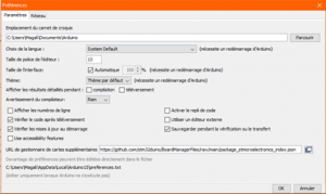
Now install the communication protocol used for the Nucleo board. For this, go to File -> Preferences, then enter this URL into the Additional Board Manager URLs: https://github.com/stm32duino/BoardManagerFiles/raw/main/package_stmicroelectronics_index.json
Click OK afterward.
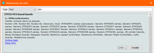
The protocol is now downloaded; to install it, go to Tools -> Board Type -> Board Manager.
In the search bar, type "stm," you should see the following screen:
Select the latest available version (here 2.4.0) and click Install. The process takes a few minutes. If everything went well, the term INSTALLED should appear.
Exercise 1: Make an LED Blink
Step 1: Connections
Connect an LED to a GPIO pin (for example, pin PA5) on the Nucleo board using a current-limiting resistor (for example, a 220-ohm resistor) in series with the LED. The positive terminal of the LED should be connected to the GPIO pin, and the negative terminal should be connected to the resistor and then to the ground (GND) of the board.
Step 2: Initialization
It's important to start with an IDE (Integrated Development Environment) that's compatible with the STM32 microcontroller. Create a new project for the Nucleo board by selecting the type of microcontroller used on your board (here STM32).
Add a source file "main.c" to your project. Add the header file for the microcontroller used in the Nucleo board (for example, stm32fxxx.h). These are the HAL library headers.
Initialize the GPIO pin for output by writing a 1 in the appropriate configuration register (for example, GPIOA->MODER |= GPIO_MODER_MODE5_0).
Step 3: Code
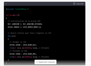
Loop indefinitely and turn on the LED by writing a 1 in the output register (for example, GPIOA->BSRR = GPIO_BSRR_BS5) for a short period, then turn off the LED by writing a 1 in the output register (for example, GPIOA->BSRR = GPIO_BSRR_BR5) for another short period. Repeat this sequence to make the LED blink.
Here's an example C code that uses the Nucleo STM32F401RE board to make an LED connected to pin PA5 blink.
Note: The codes here use pin PA5 for the LED output; of course, you need to adapt to the pin you are connected to. This code uses the "for" function to wait for a short period after each state change of the LED. The number of loops can be adjusted to change the blinking speed of the LED.
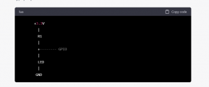
Help: Here is a typical wiring diagram for an LED on a Nucleo board.
In this diagram, R1 is the current-limiting resistor, and GPIO is the GPIO pin on the Nucleo board to which the LED is connected. The positive terminal of the LED is connected to the GPIO pin, and the negative terminal is connected to the resistor, then to the ground (GND) of the board.
Note that the value of resistor R1 depends on the supply voltage of your Nucleo board and the characteristics of the LED you are using. A typical value for the resistor is 220 ohms.
Exercise 2: Retrieve the Position of a Non-Analog Joystick
Step 1: Wiring
Plug the joystick into the Nucleo board using jumper cables. The joystick usually has two axes of movement (X and Y) and a pressure button. Each axis is connected to two pins (for example, pin A0 and pin A1), while the button is connected to another pin (for example, pin D2). Make sure to connect the joystick's correct pins to the corresponding pins on the Nucleo board.
Step 2: Initialization
Open your IDE and create a new project; then add a "main.c" source file. Next, include the header to use the HAL functions as in the previous exercise. In the "main.c" function, initialize the GPIO reading pins by writing a 0 in the appropriate configuration register (for example, GPIOA->MODER &= ~(GPIO_MODER_MODE0_Msk | GPIO_MODER_MODE1_Msk)).
Step 3: Code
Loop indefinitely and read the corresponding GPIO pins to get the joystick's position. For this, you can use the "GPIO_ReadPin" function to read the GPIO pin value. Then, you can use conditions to determine the joystick's position (for example, if the X pin's value is low and the Y pin's value is high, the joystick is in the top right corner).
Here's a C language code example that uses the Nucleo STM32F401RE board to retrieve a non-analog joystick position connected to pins PA0, PA1, and PB2.
Note: This example uses PC0 and PC1 pins for joystick inputs; you'll, of course, have to adapt to the pins you're using.
Hint: Here is a typical wiring diagram to retrieve the non-analog position of a joystick on a Nucleo board.
Note: In this diagram, R1, R2, and R3 are pull-down resistors, which set a reference state for each joystick pin. The joystick pins are connected to the Nucleo board using jumper cables. The X-Axis and Y-Axis pins are connected to two GPIO pins on the Nucleo board (for example, pins PA0 and PA1), while the Button pin is connected to another GPIO pin on the board (for example, pin PB2). The resistors R1, R2, and R3 are connected between each joystick pin and the board's ground (GND).
Note that the value of each resistor depends on the joystick and the Nucleo board you're using. A typical value for each resistor is 10k ohms.
Exercise 3: Control a Motor
Plug your joystick using the board's analog pins, then create a new project in your IDE.
Next, add the following code to initialize the input analog pins connected to the joystick.
Create a function to read the joystick's analog values with the following code.
Use the coordinate values to control the motors with the following code.
In the main program (loop), call the functions created earlier.
Once compiled and uploaded to the board, the joystick movements will control the motors in the desired directions with precision due to analog operation (more forceful movement will cause more motor movement).
These simple exercises correspond to the functions that could be useful for basic use of the Nucleo board.
Exercise 4: Retrieve the Position of a Potentiometer
For the final exercise, we thought of a very practical application for the Mini-Bee: it is about the Nucleo board's management of a potentiometer. Indeed, a drone must be able to ascend or descend vertically, implying a simultaneous increase or decrease in all rotors' speed. Thus, an analog potentiometer would allow for fine control of the device on the vertical axis.
To operate a potentiometer with a Nucleo board, here are the steps to follow:
First, you need to plug the potentiometer into a GPIO port on the board (which you should not forget to initialize, of course). Next, connect several LEDs to other GPIO pins, without forgetting to also plug in series protection resistors. These LEDs will serve to give a visual indication of the potentiometer's level of depression: the higher the analog signal emitted by the potentiometer, the more LEDs will light up.
Here is an example code that would allow you to retrieve the analog position of a potentiometer and display it using 3 LEDs.
- include"mbed.h"
AnalogIn enfoncement_potentiometre(A0);
DigitalOut led_1(D2); DigitalOut led_2(D3); DigitalOut led_3(D4);
int main() { while(1) { uint16_t valeur = enfoncement_potentiometre.read_u16(); if (valeur < 50) { led_1 = 0; led_2 = 0; led_3 = 0; } else if ((valeur >= 50) && (valeur < 2000)) { led_1 = 1; led_2 = 0; led_3 = 0; } else if ((valeur >= 2000) && (valeur < 4000)) { led_1 = 1; led_2 = 1; led_3 = 0; } else if (valeur >= 4000) { led_1 = 1; led_2 = 1; led_3 = 1; } } }
