Difference between revisions of "Minibee TRL2"
Wiki.admin (talk | contribs) |
Wiki.admin (talk | contribs) |
||
| (6 intermediate revisions by the same user not shown) | |||
| Line 1: | Line 1: | ||
| − | + | {{DISPLAYTITLE:TRL 2 – Mini-Bee}} | |
| − | + | __TOC__ | |
| − | |||
| − | |||
| − | |||
| − | |||
| − | |||
| − | |||
| − | |||
| − | |||
| − | + | <div style="border:1px solid #cfd6dd; background:#ffffff; margin-bottom:20px;"> | |
| − | + | <div style="background:#1f3a5f; color:#ffffff; padding:12px 16px; font-weight:bold;"> | |
| − | + | TRL 2 – Mini-Bee | Technology Concept Formulated | |
| − | + | </div> | |
| − | + | <div style="padding:16px;"> | |
| − | + | {| style="width:100%; border-collapse:collapse;" | |
| − | + | |- | |
| + | | style="width:48%; vertical-align:middle; padding-right:18px;" | | ||
| + | At '''TRL 2''', the '''Mini-Bee''' project moved from basic principles to a first formulated aircraft concept. | ||
| − | + | This stage focused on transforming the original VTOL idea into a more structured configuration, supported by academic studies, preliminary simulations, mock-ups, usage analysis, structural work and early technical assumptions. | |
| − | |||
| − | |||
| − | |||
| − | |||
| − | |||
| − | |||
| − | |||
| − | |||
| − | |||
| − | |||
| − | |||
| − | |||
| − | |||
| − | |||
| − | |||
| − | |||
| − | |||
| − | |||
| − | |||
| − | |||
| − | |||
| − | |||
| − | |||
| − | |||
| − | |||
| − | |||
| − | |||
| − | |||
| − | |||
| − | |||
| − | |||
| − | |||
| − | |||
| − | |||
| − | |||
| − | |||
| − | |||
| − | |||
| − | |||
| − | |||
| − | |||
| − | |||
| − | |||
| − | |||
| − | + | This page documents the collaborative work carried out during the TRL 2 phase and the historical Mini-Bee configuration studied at that stage. | |
| − | |||
| − | |||
| − | |||
| − | |||
| − | + | | style="width:52%; vertical-align:middle; text-align:center;" | | |
| − | + | [[File:MiniBee_Taxi.jpg|frameless|520px|Mini-Bee TRL2 taxi concept]] | |
| − | + | <div style="color:#4b5563; margin-top:6px;">Mini-Bee TRL2 concept visual</div> | |
| − | + | |} | |
| − | File: | + | </div> |
| − | + | </div> | |
| − | |||
| − | |||
| − | |||
| − | </ | ||
| − | == | + | == Quick project summary == |
| − | |||
| − | |||
| − | |||
| − | |||
| − | |||
| − | |||
| − | |||
| − | |||
| − | |||
| − | |||
| − | |||
| − | |||
| − | |||
| − | |||
| − | + | {| style="width:100%; border-collapse:separate; border-spacing:12px; margin-bottom:20px;" | |
| − | + | |- | |
| − | + | | style="width:25%; vertical-align:top; border:1px solid #cfd6dd; background:#f6f8fa; padding:12px;" | | |
| − | + | '''Project'''<br /> | |
| − | + | Mini-Bee | |
| − | |||
| − | |||
| − | </ | ||
| − | |||
| − | |||
| − | [[ | + | | style="width:25%; vertical-align:top; border:1px solid #cfd6dd; background:#f6f8fa; padding:12px;" | |
| − | [[ | + | '''TRL stage'''<br /> |
| + | TRL 2 – Technology Concept Formulated | ||
| + | |||
| + | | style="width:25%; vertical-align:top; border:1px solid #cfd6dd; background:#f6f8fa; padding:12px;" | | ||
| + | '''Main objective'''<br /> | ||
| + | Formulate a first VTOL aircraft concept | ||
| + | |||
| + | | style="width:25%; vertical-align:top; border:1px solid #cfd6dd; background:#f6f8fa; padding:12px;" | | ||
| + | '''Main outputs'''<br /> | ||
| + | Studies, mock-ups, simulations and first configuration data | ||
| + | |} | ||
| + | |||
| + | == Visual introduction == | ||
| + | |||
| + | {| style="width:100%; border-collapse:separate; border-spacing:12px; margin-bottom:20px;" | ||
| + | |- | ||
| + | | style="width:33%; vertical-align:top; border:1px solid #cfd6dd; background:#ffffff; padding:10px; text-align:center;" | | ||
| + | [[File:MiniBee_Taxi.jpg|frameless|300px|Mini-Bee taxi concept]] | ||
| + | <div style="margin-top:8px;">'''Taxi concept'''</div> | ||
| + | <div style="color:#4b5563;">Visual representation of the Mini-Bee TRL2 configuration.</div> | ||
| + | <div style="margin-top:8px;">[[Media:MiniBee_Taxi.jpg|Open image]]</div> | ||
| + | |||
| + | | style="width:33%; vertical-align:top; border:1px solid #cfd6dd; background:#ffffff; padding:10px; text-align:center;" | | ||
| + | [[File:Minibee 3view.jpg|frameless|300px|Mini-Bee 3-view]] | ||
| + | <div style="margin-top:8px;">'''3-view layout'''</div> | ||
| + | <div style="color:#4b5563;">Three-view representation used to clarify the aircraft configuration.</div> | ||
| + | <div style="margin-top:8px;">[[Media:Minibee 3view.jpg|Open image]]</div> | ||
| + | |||
| + | | style="width:33%; vertical-align:top; border:1px solid #cfd6dd; background:#ffffff; padding:10px; text-align:center;" | | ||
| + | [[File:Mini-Bee TRL2 by Hamza Fouatih.jpg|frameless|300px|Mini-Bee TRL2 mock-up]] | ||
| + | <div style="margin-top:8px;">'''3D mock-up'''</div> | ||
| + | <div style="color:#4b5563;">Digital mock-up supporting concept formulation and communication.</div> | ||
| + | <div style="margin-top:8px;">[[Media:Mini-Bee TRL2 by Hamza Fouatih.jpg|Open image]]</div> | ||
| + | |} | ||
| + | |||
| + | == Project overview == | ||
| + | |||
| + | '''TRL 2 – Technology Concept Formulated''' corresponds to the stage where the Mini-Bee project started to define a credible technical concept from the initial TRL 1 observations. | ||
| + | |||
| + | At this stage, the goal was not yet to validate a prototype. The objective was to describe a possible aircraft configuration, identify the main technical domains to study, and distribute work between academic contributors. | ||
| + | |||
| + | <div style="border-left:4px solid #1f3a5f; background:#f6f8fa; padding:12px; margin:16px 0;"> | ||
| + | '''TRL 2 objective:''' formulate a first coherent Mini-Bee aircraft concept, supported by preliminary technical studies, mock-ups, simulations and mission assumptions. | ||
| + | </div> | ||
| + | |||
| + | == Work done during TRL 2 == | ||
| + | |||
| + | During TRL 2, the Mini-Bee project benefited from a broad collaborative effort involving universities, engineering schools and technical contributors. | ||
| + | |||
| + | The work covered several technical and operational domains: | ||
| + | |||
| + | * aeronautical simulation; | ||
| + | * use cases and mission analysis; | ||
| + | * propulsion and engine assumptions; | ||
| + | * structural design; | ||
| + | * mechanical mock-up development; | ||
| + | * aerodynamic optimisation; | ||
| + | * equipment studies; | ||
| + | * human-machine interface; | ||
| + | * seats and safety; | ||
| + | * sensors and electromagnetic compatibility; | ||
| + | * rotor and power-chain optimisation; | ||
| + | * landing gear studies. | ||
| + | |||
| + | == Academic and technical contributions == | ||
| + | |||
| + | {| class="wikitable" style="width:100%;" | ||
| + | |- | ||
| + | ! style="width:22%; background:#eef1f4;" | Contributor | ||
| + | ! style="width:28%; background:#eef1f4;" | Main contribution | ||
| + | ! style="background:#eef1f4;" | Documents | ||
| + | |- | ||
| + | | '''Centrale Supélec''' | ||
| + | | Aeronautical simulation | ||
| + | | | ||
| + | * [[File:201706 pres ECP aero.pdf]] | ||
| + | * [[File:Suivi code 2017 3.0.pdf]] | ||
| + | * [[File:Guide fonction code Version 1.0 ECP2016.pdf]] | ||
| + | |- | ||
| + | | '''Estaca''' | ||
| + | | Usages and engines | ||
| + | | | ||
| + | * [[File:Rapport projet 5A Mini Bee intérieur.pdf]] | ||
| + | * [[File:Masse Coûts approx Mini-Bee version ambulance.xlsx]] | ||
| + | * [[File:2017 01 24 Planches VIP.pdf]] | ||
| + | * [[File:Rapport projet Mini-Bee.pdf]] | ||
| + | * [[File:BEE-PLANE REPORT 2016-2017 ISIEB v2.pdf]] | ||
| + | |- | ||
| + | | '''Estaca SQY 4A''' | ||
| + | | Structure | ||
| + | | | ||
| + | * [[File:RapportdeProjet structure estaca 4A 2017.pdf]] | ||
| + | * [[File:RapportdeProjet1ersemestre.pdf]] | ||
| + | * [[File:Soutenance 132F01.pdf]] | ||
| + | * [[File:Soutenance du 2ème semestre (21F042F2017).pdf]] | ||
| + | |- | ||
| + | | '''Supmeca''' | ||
| + | | Structural and mechanical mock-up | ||
| + | | | ||
| + | * [[File:SUPMECA FINAL 201706Bourget.pdf]] | ||
| + | * [[File:Supmeca MotorisationMiniBee 201706Bourget.pdf]] | ||
| + | * [[File:Mini-Bee Project 2017 - Aerodynamic optimisation.pdf]] | ||
| + | * [[File:Présentation Mini-Bee optimisation aérodynamique 2017.pdf]] | ||
| + | * [[File:Mini-bee soutenance2302 final.pdf]] | ||
| + | * [[File:Rapport Mini-Bee v5-finale.pdf]] | ||
| + | |- | ||
| + | | '''ENSTA Bretagne''' | ||
| + | | Scale flying mock-up and project presentation | ||
| + | | | ||
| + | * [[File:ENSTA Bretagne 201706Bourget.pdf]] | ||
| + | |- | ||
| + | | '''Polito''' | ||
| + | | Equipment studies | ||
| + | | | ||
| + | * [[File:Final Report Polito 23 02 17.pdf]] | ||
| + | * [[File:Polito Supmeca presentation 23 02 17.pdf]] | ||
| + | |- | ||
| + | | '''ENSEA''' | ||
| + | | Human-machine interface | ||
| + | | | ||
| + | * [[File:ENSEA 201706Bourget.pdf]] | ||
| + | |- | ||
| + | | '''INSA''' | ||
| + | | Seat and occupant integration | ||
| + | | | ||
| + | * [[File:INSA pres NAE.pdf]] | ||
| + | |- | ||
| + | | '''IUT Le Havre''' | ||
| + | | Tilt mechanism studies | ||
| + | | | ||
| + | * [[File:IUT LeHavre 201706Bourget.pdf]] | ||
| + | |- | ||
| + | | '''IUT Rouen''' | ||
| + | | Sensors and electromagnetic compatibility | ||
| + | | | ||
| + | * [[File:CEM IUT Rouen 201706Bourget.pdf]] | ||
| + | * [[File:IUT Rouen Capteur 201706Bourget.pdf]] | ||
| + | * [[File:Présentation24-06-17-2 IUT ROUEN 201706Bourget.pdf]] | ||
| + | |- | ||
| + | | '''IUT Caen''' | ||
| + | | Rotors and power-chain optimisation | ||
| + | | | ||
| + | * [[File:IUT CAEN PstBgt 201706Bourget.pdf]] | ||
| + | |- | ||
| + | | '''Esitech''' | ||
| + | | Technical contribution | ||
| + | | | ||
| + | * [[File:ESITECH 201706Bourget.pdf]] | ||
| + | |- | ||
| + | | '''Lycée Diderot''' | ||
| + | | Rear landing gear | ||
| + | | | ||
| + | * [[File:Projet Personnelle Mini Bee Sagithan DEVAKUMARAN.pdf]] | ||
| + | * [[File:Rapport de projet partie personelle SZASZ.pdf]] | ||
| + | * [[File:DIDEROT 201706Bourget.pdf]] | ||
| + | |} | ||
| + | |||
| + | == Mock-up display == | ||
| + | |||
| + | A digital 3D mock-up was created to support the understanding of the Mini-Bee configuration during the TRL 2 phase. | ||
| + | |||
| + | <div style="border:1px solid #cfd6dd; background:#f6f8fa; padding:12px; margin:16px 0;"> | ||
| + | '''3D mock-up:''' [https://sketchfab.com/models/d61585148d7a4447835064cb5d742449 Mini-Bee 3D mock-up] by Hamza Fouatih. | ||
| + | </div> | ||
| + | |||
| + | == Mini-Bee TRL 2 configuration visuals == | ||
| + | |||
| + | <gallery mode="packed" heights="180"> | ||
| + | File:MiniBee_Taxi.jpg|Taxi concept | ||
| + | File:Minibee 3view.jpg|Three-view layout | ||
| + | File:1.jpg|Early TRL2 visual | ||
| + | File:Minibee 3view - front.jpg|Front view | ||
| + | File:Minibee 3view - side.jpg|Side view | ||
| + | File:Minibee 3view - top.jpg|Top view | ||
| + | File:Mini-Bee TRL2 by Hamza Fouatih.jpg|3D mock-up by Hamza Fouatih | ||
| + | </gallery> | ||
| + | |||
| + | == Concept formulation at TRL 2 == | ||
| + | |||
| + | At TRL 2, the Mini-Bee concept was described as a hybrid VTOL aircraft intended to combine vertical take-off capability, distributed propulsion and mission flexibility. | ||
| + | |||
| + | The configuration studied at this stage included a larger aircraft concept than later versions of the Mini-Bee. | ||
| + | |||
| + | <div style="border:1px solid #cfd6dd; background:#f6f8fa; padding:12px; margin:16px 0;"> | ||
| + | '''Important note:''' this page documents the historical TRL 2 configuration. Later TRL levels may describe updated Mini-Bee configurations, including revised rotor architecture, propulsion choices, mass assumptions and mission scope. | ||
| + | </div> | ||
| + | |||
| + | == General characteristics == | ||
| + | |||
| + | {| class="wikitable" style="width:100%;" | ||
| + | |- | ||
| + | ! style="width:35%; background:#eef1f4;" | Parameter | ||
| + | ! style="background:#eef1f4;" | TRL 2 configuration | ||
| + | |- | ||
| + | | '''Crew''' | ||
| + | | 2 pilots | ||
| + | |- | ||
| + | | '''Capacity''' | ||
| + | | From 1 passenger and 1 patient to 3 passengers and 2 patients with central module | ||
| + | |- | ||
| + | | '''Length''' | ||
| + | | 6.01 m / 19 ft 9 in | ||
| + | |- | ||
| + | | '''Height''' | ||
| + | | 2.3 m / 7 ft 7 in | ||
| + | |- | ||
| + | | '''Empty weight''' | ||
| + | | 850 kg / 1,873 lb | ||
| + | |- | ||
| + | | '''Maximum take-off weight''' | ||
| + | | 1,200 kg / 2,643 lb | ||
| + | |- | ||
| + | | '''Powerplant''' | ||
| + | | Piston engine for 250 kW at take-off and electric motors | ||
| + | |- | ||
| + | | '''Central rotor area''' | ||
| + | | 12.6 m² / 41.5 sq ft | ||
| + | |- | ||
| + | | '''Wing rotor area''' | ||
| + | | 10.6 m² / 35 sq ft | ||
| + | |- | ||
| + | | '''Wing area''' | ||
| + | | 8.66 m² / 28.5 sq ft | ||
| + | |- | ||
| + | | '''Airfoil''' | ||
| + | | Davis basic B-24 | ||
| + | |- | ||
| + | | '''Fuel capacity''' | ||
| + | | 150 l | ||
| + | |} | ||
| + | |||
| + | == Performance assumptions == | ||
| + | |||
| + | {| class="wikitable" style="width:100%;" | ||
| + | |- | ||
| + | ! style="width:35%; background:#eef1f4;" | Parameter | ||
| + | ! style="background:#eef1f4;" | TRL 2 assumption | ||
| + | |- | ||
| + | | '''Cruise speed''' | ||
| + | | 250 km/h / 155 mph / 135 kn | ||
| + | |- | ||
| + | | '''Maximum speed''' | ||
| + | | 300 km/h / 186 mph / 162 kn | ||
| + | |- | ||
| + | | '''Range''' | ||
| + | | 500 km / 311 mi / 270 nm | ||
| + | |- | ||
| + | | '''Service ceiling''' | ||
| + | | 4,000 m / 13,000 ft | ||
| + | |- | ||
| + | | '''Rate of climb''' | ||
| + | | 6.45 m/s / 1,270 ft/min | ||
| + | |} | ||
| + | |||
| + | == Additional concept visual == | ||
| + | |||
| + | <div style="border:1px solid #cfd6dd; background:#ffffff; padding:12px; margin:16px 0; text-align:center;"> | ||
| + | [[File:Minibeev14_image.png|frameless|520px|Mini-Bee v14 concept image]] | ||
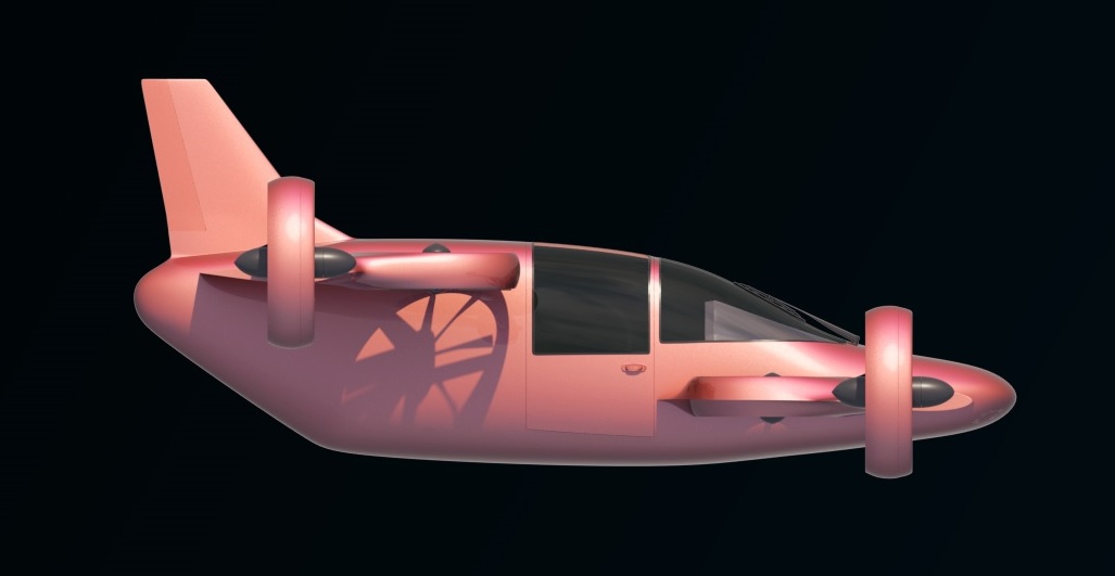
| + | <div style="color:#4b5563; margin-top:6px;">Mini-Bee concept image used during the early configuration studies</div> | ||
| + | <div style="margin-top:8px;">[[Media:Minibeev14_image.png|Open image]]</div> | ||
| + | </div> | ||
| + | |||
| + | == TRL 2 outputs == | ||
| + | |||
| + | TRL 2 produced a first structured basis for the Mini-Bee aircraft concept. | ||
| + | |||
| + | {| style="width:100%; border-collapse:separate; border-spacing:12px; margin:16px 0;" | ||
| + | |- | ||
| + | | style="width:33%; vertical-align:top; border:1px solid #cfd6dd; background:#ffffff; padding:12px;" | | ||
| + | '''Concept definition''' | ||
| + | |||
| + | A first aircraft configuration was described, including dimensions, mass assumptions, rotor areas and performance targets. | ||
| + | |||
| + | | style="width:33%; vertical-align:top; border:1px solid #cfd6dd; background:#ffffff; padding:12px;" | | ||
| + | '''Collaborative studies''' | ||
| + | |||
| + | Several academic teams contributed to simulation, structure, equipment, HMI, sensors, rotors and mechanical studies. | ||
| + | |||
| + | | style="width:33%; vertical-align:top; border:1px solid #cfd6dd; background:#ffffff; padding:12px;" | | ||
| + | '''Visual and mock-up support''' | ||
| + | |||
| + | The TRL 2 stage included 3D mock-ups, three-view layouts and visual representations to clarify the aircraft concept. | ||
| + | |} | ||
| + | |||
| + | == What TRL 2 clarified == | ||
| + | |||
| + | {| style="width:100%; border-collapse:separate; border-spacing:12px; margin:16px 0;" | ||
| + | |- | ||
| + | | style="width:50%; vertical-align:top; border:1px solid #cfd6dd; background:#f6f8fa; padding:12px;" | | ||
| + | '''Clarified during TRL 2''' | ||
| + | |||
| + | * first Mini-Bee aircraft configuration; | ||
| + | * initial mission and use-case logic; | ||
| + | * preliminary performance assumptions; | ||
| + | * early propulsion and energy direction; | ||
| + | * first structural studies; | ||
| + | * mock-up and 3D representation; | ||
| + | * distribution of work between academic contributors. | ||
| + | |||
| + | | style="width:50%; vertical-align:top; border:1px solid #cfd6dd; background:#f6f8fa; padding:12px;" | | ||
| + | '''Still open after TRL 2''' | ||
| + | |||
| + | * validated propulsion architecture; | ||
| + | * final rotor configuration; | ||
| + | * detailed structural sizing; | ||
| + | * complete flight control architecture; | ||
| + | * power-chain validation; | ||
| + | * certification strategy; | ||
| + | * experimental proof of concept. | ||
| + | |} | ||
| + | |||
| + | == TRL 2 maturity logic == | ||
| + | |||
| + | The TRL 2 phase helped transform the Mini-Bee from an early idea into a project with a visible concept structure. | ||
| + | |||
| + | {| style="width:100%; border-collapse:collapse; text-align:center; margin:16px 0 20px 0;" | ||
| + | |- | ||
| + | | style="background:#1f3a5f; color:#ffffff; border:1px solid #cfd6dd; padding:10px; font-weight:bold;" | 1. Formulate | ||
| + | | style="background:#f3f5f7; border:1px solid #cfd6dd; padding:10px;" | 2. Assign studies | ||
| + | | style="background:#f3f5f7; border:1px solid #cfd6dd; padding:10px;" | 3. Model | ||
| + | | style="background:#f3f5f7; border:1px solid #cfd6dd; padding:10px;" | 4. Compare | ||
| + | | style="background:#f3f5f7; border:1px solid #cfd6dd; padding:10px;" | 5. Prepare TRL 3 | ||
| + | |- | ||
| + | | style="border:1px solid #cfd6dd; padding:8px;" | First aircraft concept | ||
| + | | style="border:1px solid #cfd6dd; padding:8px;" | Academic work packages | ||
| + | | style="border:1px solid #cfd6dd; padding:8px;" | Mock-ups and simulations | ||
| + | | style="border:1px solid #cfd6dd; padding:8px;" | Mission and technology assumptions | ||
| + | | style="border:1px solid #cfd6dd; padding:8px;" | Toward proof of concept | ||
| + | |} | ||
| + | |||
| + | == Questions to solve before TRL 3 == | ||
| + | |||
| + | Before moving from TRL 2 to TRL 3, several questions had to be addressed: | ||
| + | |||
| + | * Which aircraft configuration should be retained for proof-of-concept work? | ||
| + | * Which propulsion architecture is realistic for vertical flight? | ||
| + | * What rotor distribution provides enough lift and redundancy? | ||
| + | * What structure can support the rotor system and mission loads? | ||
| + | * How should the flight control logic be tested? | ||
| + | * What mock-up or demonstrator is required to validate the main assumptions? | ||
| + | * Which mission should drive the next stage of development? | ||
| + | |||
| + | == Image files used on this page == | ||
| + | |||
| + | {| class="wikitable" style="width:100%;" | ||
| + | |- | ||
| + | ! style="width:35%; background:#eef1f4;" | Wiki file name | ||
| + | ! style="width:25%; background:#eef1f4;" | Use in page | ||
| + | ! style="background:#eef1f4;" | Link | ||
| + | |- | ||
| + | | MiniBee_Taxi.jpg | ||
| + | | Hero image, visual introduction and gallery | ||
| + | | [[Media:MiniBee_Taxi.jpg|Open image]] | ||
| + | |- | ||
| + | | Minibee 3view.jpg | ||
| + | | Visual introduction and gallery | ||
| + | | [[Media:Minibee 3view.jpg|Open image]] | ||
| + | |- | ||
| + | | 1.jpg | ||
| + | | Gallery | ||
| + | | [[Media:1.jpg|Open image]] | ||
| + | |- | ||
| + | | Minibee 3view - front.jpg | ||
| + | | Gallery | ||
| + | | [[Media:Minibee 3view - front.jpg|Open image]] | ||
| + | |- | ||
| + | | Minibee 3view - side.jpg | ||
| + | | Gallery | ||
| + | | [[Media:Minibee 3view - side.jpg|Open image]] | ||
| + | |- | ||
| + | | Minibee 3view - top.jpg | ||
| + | | Gallery | ||
| + | | [[Media:Minibee 3view - top.jpg|Open image]] | ||
| + | |- | ||
| + | | Mini-Bee TRL2 by Hamza Fouatih.jpg | ||
| + | | Visual introduction and gallery | ||
| + | | [[Media:Mini-Bee TRL2 by Hamza Fouatih.jpg|Open image]] | ||
| + | |- | ||
| + | | Minibeev14_image.png | ||
| + | | Additional concept visual | ||
| + | | [[Media:Minibeev14_image.png|Open image]] | ||
| + | |} | ||
| + | |||
| + | == Why TRL 2 mattered == | ||
| + | |||
| + | TRL 2 was a key step because it gave the Mini-Bee project its first formulated technical identity. | ||
| + | |||
| + | It created a common concept basis for academic partners, contributors and project coordination. | ||
| + | It also allowed the project to move from early intuition toward structured design studies and future proof-of-concept work. | ||
| + | |||
| + | == Transition to the next stage == | ||
| + | |||
| + | <div style="border:1px solid #cfd6dd; background:#f6f8fa; padding:14px; margin-top:16px;"> | ||
| + | '''Next maturity step:''' TRL 3 – Experimental Proof of Concept. | ||
| + | </div> | ||
| + | |||
| + | At TRL 3, the project moves from concept formulation to first analytical or experimental evidence supporting the main technical assumptions. | ||
| + | |||
| + | == See also == | ||
| + | |||
| + | * [[Technology Readiness Level (TRL)|General page - TRL 1 ]] | ||
| + | * [[Minibee TRL1 |Minibee TRL1 ]] | ||
| + | * [[Minibee TRL3|Minibee TRL3 ]] | ||
| + | * [[Mini-Bee|Mini-Bee project]] | ||
Latest revision as of 11:17, 7 May 2026
TRL 2 – Mini-Bee | Technology Concept Formulated
|
At TRL 2, the Mini-Bee project moved from basic principles to a first formulated aircraft concept. This stage focused on transforming the original VTOL idea into a more structured configuration, supported by academic studies, preliminary simulations, mock-ups, usage analysis, structural work and early technical assumptions. This page documents the collaborative work carried out during the TRL 2 phase and the historical Mini-Bee configuration studied at that stage. |
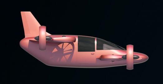
Mini-Bee TRL2 concept visual
|

Quick project summary
|
Project |
TRL stage |
Main objective |
Main outputs |
Visual introduction
|
Taxi concept
Visual representation of the Mini-Bee TRL2 configuration.
|
3-view layout
Three-view representation used to clarify the aircraft configuration.
|
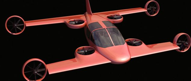
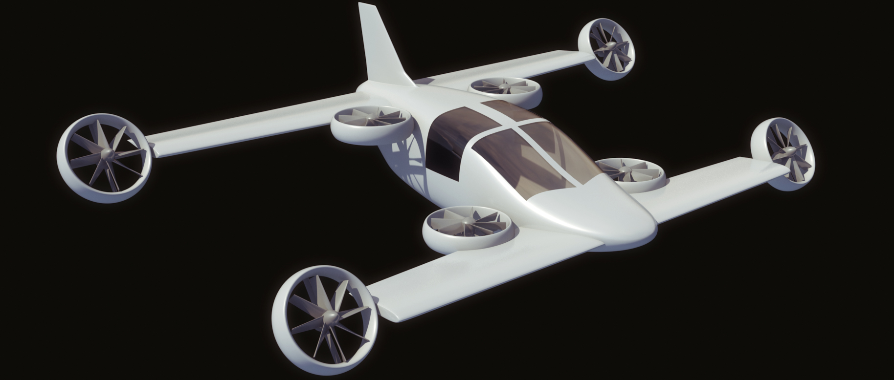
3D mock-up
Digital mock-up supporting concept formulation and communication.
|


Project overview
TRL 2 – Technology Concept Formulated corresponds to the stage where the Mini-Bee project started to define a credible technical concept from the initial TRL 1 observations.
At this stage, the goal was not yet to validate a prototype. The objective was to describe a possible aircraft configuration, identify the main technical domains to study, and distribute work between academic contributors.
TRL 2 objective: formulate a first coherent Mini-Bee aircraft concept, supported by preliminary technical studies, mock-ups, simulations and mission assumptions.
Work done during TRL 2
During TRL 2, the Mini-Bee project benefited from a broad collaborative effort involving universities, engineering schools and technical contributors.
The work covered several technical and operational domains:
- aeronautical simulation;
- use cases and mission analysis;
- propulsion and engine assumptions;
- structural design;
- mechanical mock-up development;
- aerodynamic optimisation;
- equipment studies;
- human-machine interface;
- seats and safety;
- sensors and electromagnetic compatibility;
- rotor and power-chain optimisation;
- landing gear studies.
Academic and technical contributions
| Contributor | Main contribution | Documents |
|---|---|---|
| Centrale Supélec | Aeronautical simulation | |
| Estaca | Usages and engines | |
| Estaca SQY 4A | Structure | |
| Supmeca | Structural and mechanical mock-up | |
| ENSTA Bretagne | Scale flying mock-up and project presentation | |
| Polito | Equipment studies | |
| ENSEA | Human-machine interface | |
| INSA | Seat and occupant integration | |
| IUT Le Havre | Tilt mechanism studies | |
| IUT Rouen | Sensors and electromagnetic compatibility | |
| IUT Caen | Rotors and power-chain optimisation | |
| Esitech | Technical contribution | |
| Lycée Diderot | Rear landing gear |
Mock-up display
A digital 3D mock-up was created to support the understanding of the Mini-Bee configuration during the TRL 2 phase.
3D mock-up: Mini-Bee 3D mock-up by Hamza Fouatih.
Mini-Bee TRL 2 configuration visuals
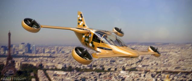
Taxi concept
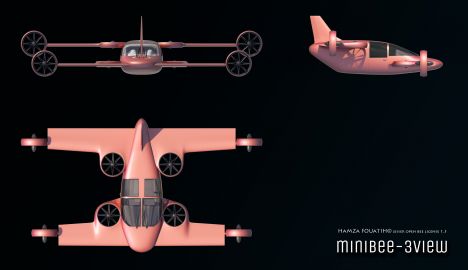
Three-view layout
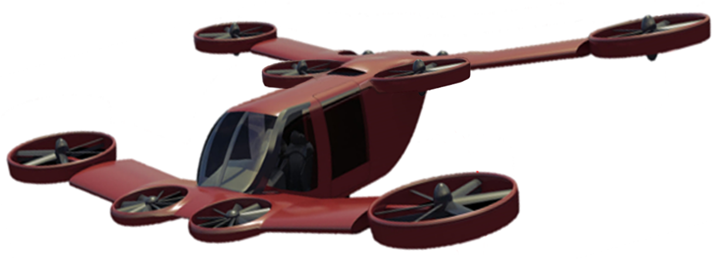
Early TRL2 visual
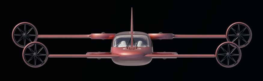
Front view
Side view

Top view

3D mock-up by Hamza Fouatih


Concept formulation at TRL 2
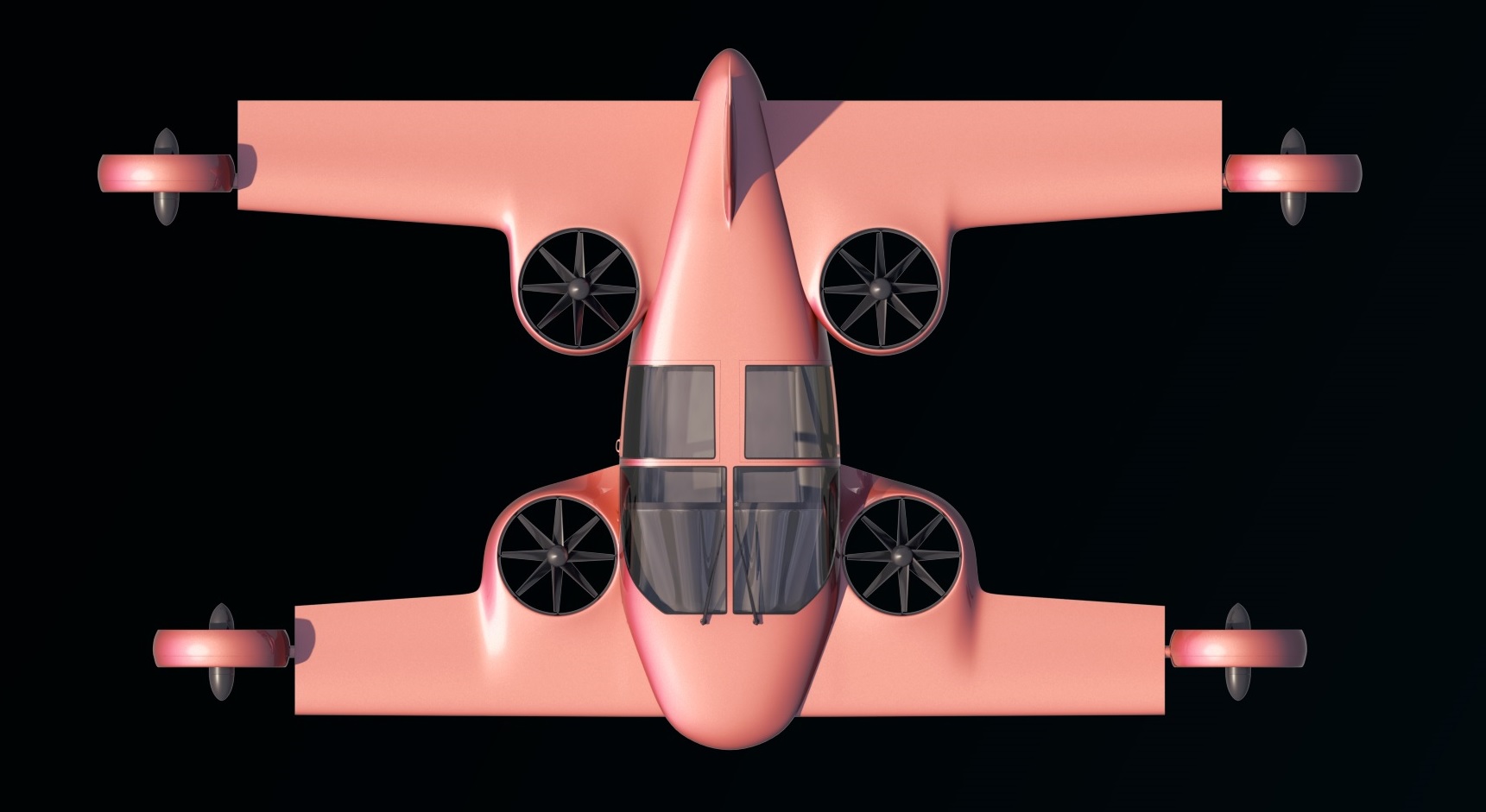
At TRL 2, the Mini-Bee concept was described as a hybrid VTOL aircraft intended to combine vertical take-off capability, distributed propulsion and mission flexibility.
The configuration studied at this stage included a larger aircraft concept than later versions of the Mini-Bee.
Important note: this page documents the historical TRL 2 configuration. Later TRL levels may describe updated Mini-Bee configurations, including revised rotor architecture, propulsion choices, mass assumptions and mission scope.
General characteristics
| Parameter | TRL 2 configuration |
|---|---|
| Crew | 2 pilots |
| Capacity | From 1 passenger and 1 patient to 3 passengers and 2 patients with central module |
| Length | 6.01 m / 19 ft 9 in |
| Height | 2.3 m / 7 ft 7 in |
| Empty weight | 850 kg / 1,873 lb |
| Maximum take-off weight | 1,200 kg / 2,643 lb |
| Powerplant | Piston engine for 250 kW at take-off and electric motors |
| Central rotor area | 12.6 m² / 41.5 sq ft |
| Wing rotor area | 10.6 m² / 35 sq ft |
| Wing area | 8.66 m² / 28.5 sq ft |
| Airfoil | Davis basic B-24 |
| Fuel capacity | 150 l |
Performance assumptions
| Parameter | TRL 2 assumption |
|---|---|
| Cruise speed | 250 km/h / 155 mph / 135 kn |
| Maximum speed | 300 km/h / 186 mph / 162 kn |
| Range | 500 km / 311 mi / 270 nm |
| Service ceiling | 4,000 m / 13,000 ft |
| Rate of climb | 6.45 m/s / 1,270 ft/min |
Additional concept visual

TRL 2 outputs
TRL 2 produced a first structured basis for the Mini-Bee aircraft concept.
|
Concept definition A first aircraft configuration was described, including dimensions, mass assumptions, rotor areas and performance targets. |
Collaborative studies Several academic teams contributed to simulation, structure, equipment, HMI, sensors, rotors and mechanical studies. |
Visual and mock-up support The TRL 2 stage included 3D mock-ups, three-view layouts and visual representations to clarify the aircraft concept. |
What TRL 2 clarified
|
Clarified during TRL 2
|
Still open after TRL 2
|
TRL 2 maturity logic
The TRL 2 phase helped transform the Mini-Bee from an early idea into a project with a visible concept structure.
| 1. Formulate | 2. Assign studies | 3. Model | 4. Compare | 5. Prepare TRL 3 |
| First aircraft concept | Academic work packages | Mock-ups and simulations | Mission and technology assumptions | Toward proof of concept |
Questions to solve before TRL 3
Before moving from TRL 2 to TRL 3, several questions had to be addressed:
- Which aircraft configuration should be retained for proof-of-concept work?
- Which propulsion architecture is realistic for vertical flight?
- What rotor distribution provides enough lift and redundancy?
- What structure can support the rotor system and mission loads?
- How should the flight control logic be tested?
- What mock-up or demonstrator is required to validate the main assumptions?
- Which mission should drive the next stage of development?
Image files used on this page
| Wiki file name | Use in page | Link |
|---|---|---|
| MiniBee_Taxi.jpg | Hero image, visual introduction and gallery | Open image |
| Minibee 3view.jpg | Visual introduction and gallery | Open image |
| 1.jpg | Gallery | Open image |
| Minibee 3view - front.jpg | Gallery | Open image |
| Minibee 3view - side.jpg | Gallery | Open image |
| Minibee 3view - top.jpg | Gallery | Open image |
| Mini-Bee TRL2 by Hamza Fouatih.jpg | Visual introduction and gallery | Open image |
| Minibeev14_image.png | Additional concept visual | Open image |
Why TRL 2 mattered
TRL 2 was a key step because it gave the Mini-Bee project its first formulated technical identity.
It created a common concept basis for academic partners, contributors and project coordination. It also allowed the project to move from early intuition toward structured design studies and future proof-of-concept work.
Transition to the next stage
Next maturity step: TRL 3 – Experimental Proof of Concept.
At TRL 3, the project moves from concept formulation to first analytical or experimental evidence supporting the main technical assumptions.