Difference between revisions of "Minibee TRL0"
Wiki.admin (talk | contribs) |
Wiki.admin (talk | contribs) |
||
| (5 intermediate revisions by the same user not shown) | |||
| Line 1: | Line 1: | ||
| + | {{DISPLAYTITLE:TRL 0 – Mini-Bee}} | ||
| + | |||
| + | [[Minibee TRL1 |TRL 1 – Mini-Bee ]] | ||
| + | |||
<div style="border:1px solid #cfd6dd; background:#ffffff; margin-bottom:22px;"> | <div style="border:1px solid #cfd6dd; background:#ffffff; margin-bottom:22px;"> | ||
<div style="background:#1f3a5f; color:#ffffff; padding:12px 16px; font-weight:bold; font-size:120%;"> | <div style="background:#1f3a5f; color:#ffffff; padding:12px 16px; font-weight:bold; font-size:120%;"> | ||
TRL 0 – Mini-Bee | Concept Origin and Early Intuition | TRL 0 – Mini-Bee | Concept Origin and Early Intuition | ||
</div> | </div> | ||
| + | |||
| + | __TOC__ | ||
| + | |||
| + | |||
<div style="padding:16px;"> | <div style="padding:16px;"> | ||
| Line 13: | Line 21: | ||
It documents the period before the formal Technology Readiness Level scale begins at '''TRL 1 – Basic Principles Observed'''. | It documents the period before the formal Technology Readiness Level scale begins at '''TRL 1 – Basic Principles Observed'''. | ||
| − | This page gathers the first Mini-Bee concept materials: early mission needs, hand sketches, preliminary aircraft assumptions, first sizing logic and early propulsion discussions. | + | This page gathers the first Mini-Bee concept materials: early mission needs, first aircraft intuition, hand sketches, preliminary aircraft assumptions, first sizing logic and early propulsion discussions. |
| − | The material presented here is historical. It does not represent the | + | The material presented here is historical. It does not represent the current Mini-Bee architecture. Its purpose is to explain how the project started and how the early concept progressively moved toward a hybrid VTOL aircraft approach. |
| style="width:52%; vertical-align:middle; text-align:center;" | | | style="width:52%; vertical-align:middle; text-align:center;" | | ||
| Line 24: | Line 32: | ||
</div> | </div> | ||
</div> | </div> | ||
| − | |||
| − | |||
| − | |||
| − | |||
| − | |||
== Quick project summary == | == Quick project summary == | ||
| Line 52: | Line 55: | ||
<div style="border-left:4px solid #1f3a5f; background:#f6f8fa; padding:12px; margin:16px 0;"> | <div style="border-left:4px solid #1f3a5f; background:#f6f8fa; padding:12px; margin:16px 0;"> | ||
| − | '''Important note:''' TRL 0 is not part of the standard TRL scale. It is used here as a practical archive stage to describe the pre-TRL concept work before TRL 1. | + | '''Important note:''' TRL 0 is not part of the standard TRL scale. It is used here as a practical archive stage to describe the Mini-Bee pre-TRL concept work before TRL 1. |
</div> | </div> | ||
| − | == Visual | + | == Visual archive == |
{| style="width:100%; border-collapse:separate; border-spacing:12px; margin-bottom:22px;" | {| style="width:100%; border-collapse:separate; border-spacing:12px; margin-bottom:22px;" | ||
|- | |- | ||
| − | | style="width:33%; vertical-align:top; border:1px solid #cfd6dd; background:#ffffff; padding:10px; text-align:center;" | | + | | style="width:33.33%; vertical-align:top; border:1px solid #cfd6dd; background:#ffffff; padding:10px; text-align:center;" | |
[[File:mb_trl0_early_3d_render.png|frameless|300px|Early Mini-Bee digital concept]] | [[File:mb_trl0_early_3d_render.png|frameless|300px|Early Mini-Bee digital concept]] | ||
<div style="margin-top:8px;">'''Early digital concept'''</div> | <div style="margin-top:8px;">'''Early digital concept'''</div> | ||
| Line 65: | Line 68: | ||
<div style="margin-top:8px;">[[Media:mb_trl0_early_3d_render.png|Open image]]</div> | <div style="margin-top:8px;">[[Media:mb_trl0_early_3d_render.png|Open image]]</div> | ||
| − | | style="width:33%; vertical-align:top; border:1px solid #cfd6dd; background:#ffffff; padding:10px; text-align:center;" | | + | | style="width:33.33%; vertical-align:top; border:1px solid #cfd6dd; background:#ffffff; padding:10px; text-align:center;" | |
[[File:mb_trl0_hand_sketch_01.png|frameless|300px|Mini-Bee first hand sketch]] | [[File:mb_trl0_hand_sketch_01.png|frameless|300px|Mini-Bee first hand sketch]] | ||
| − | <div style="margin-top:8px;">''' | + | <div style="margin-top:8px;">'''Initial sketch sheet'''</div> |
| − | <div style="color:#4b5563;"> | + | <div style="color:#4b5563;">First aircraft layout intuition with early views.</div> |
<div style="margin-top:8px;">[[Media:mb_trl0_hand_sketch_01.png|Open image]]</div> | <div style="margin-top:8px;">[[Media:mb_trl0_hand_sketch_01.png|Open image]]</div> | ||
| − | | style="width:33%; vertical-align:top; border:1px solid #cfd6dd; background:#ffffff; padding:10px; text-align:center;" | | + | | style="width:33.33%; vertical-align:top; border:1px solid #cfd6dd; background:#ffffff; padding:10px; text-align:center;" | |
| − | [[File: | + | [[File:mb_trl0_hand_sketch_02.png|frameless|300px|Mini-Bee alternative early configuration]] |
| − | <div style="margin-top:8px;">''' | + | <div style="margin-top:8px;">'''Alternative configuration'''</div> |
| − | <div style="color:#4b5563;"> | + | <div style="color:#4b5563;">Early exploration of another possible aircraft layout.</div> |
| − | <div style="margin-top:8px;">[[Media: | + | <div style="margin-top:8px;">[[Media:mb_trl0_hand_sketch_02.png|Open image]]</div> |
|} | |} | ||
| Line 107: | Line 110: | ||
'''Mobility''' | '''Mobility''' | ||
| − | The concept aimed to operate from many types of locations, not only from conventional runways. | + | The aircraft concept aimed to operate from many types of locations, not only from conventional runways. |
| style="width:33%; vertical-align:top; border:1px solid #cfd6dd; background:#ffffff; padding:12px;" | | | style="width:33%; vertical-align:top; border:1px solid #cfd6dd; background:#ffffff; padding:12px;" | | ||
| Line 154: | Line 157: | ||
The first hand sketches helped define the initial visual intuition of the aircraft. | The first hand sketches helped define the initial visual intuition of the aircraft. | ||
| − | They explored | + | They explored early aircraft proportions, basic configuration logic and possible layout directions. At this stage, the aim was not to freeze the design, but to make the concept visible enough to start technical discussions. |
| − | <gallery mode="packed" heights=" | + | <gallery mode="packed" heights="190"> |
File:mb_trl0_hand_sketch_01.png|Initial sketch sheet – first layout intuition | File:mb_trl0_hand_sketch_01.png|Initial sketch sheet – first layout intuition | ||
File:mb_trl0_hand_sketch_02.png|Alternative early configuration | File:mb_trl0_hand_sketch_02.png|Alternative early configuration | ||
| − | |||
</gallery> | </gallery> | ||
| Line 200: | Line 202: | ||
The initial wing evaluation used a simple aerodynamic approach to estimate the chord needed for different stall speed assumptions. | The initial wing evaluation used a simple aerodynamic approach to estimate the chord needed for different stall speed assumptions. | ||
| − | This work helped transform the early visual idea into a first sizing discussion. | + | This work helped transform the early visual idea into a first sizing discussion. The objective was to connect the aircraft mass assumption, the desired stall speed and the first wing geometry hypotheses. |
| − | + | {| class="wikitable" style="width:100%;" | |
| − | + | |- | |
| − | + | ! style="width:30%; background:#eef1f4;" | Study point | |
| − | + | ! style="background:#eef1f4;" | TRL 0 purpose | |
| + | |- | ||
| + | | '''Wing area''' | ||
| + | | Estimate the first order wing surface required to support the aircraft during conventional flight. | ||
| + | |- | ||
| + | | '''Stall speed''' | ||
| + | | Compare different stall speed assumptions and their impact on wing chord. | ||
| + | |- | ||
| + | | '''Aircraft mass''' | ||
| + | | Understand how the early MTOW assumption influenced the required lift surface. | ||
| + | |- | ||
| + | | '''Design consequence''' | ||
| + | | Identify whether the initial aircraft intuition remained compatible with practical wing dimensions. | ||
| + | |} | ||
| − | == | + | == Propulsion evaluation == |
The early propulsion work explored two complementary questions. | The early propulsion work explored two complementary questions. | ||
| Line 213: | Line 228: | ||
First, the thermal engine could potentially support cruise power or electrical generation. Second, the electric motors had to be assessed against the demanding power-to-weight requirements of VTOL flight. | First, the thermal engine could potentially support cruise power or electrical generation. Second, the electric motors had to be assessed against the demanding power-to-weight requirements of VTOL flight. | ||
| − | + | {| class="wikitable" style="width:100%;" | |
| − | + | |- | |
| − | + | ! style="width:30%; background:#eef1f4;" | Propulsion topic | |
| − | + | ! style="background:#eef1f4;" | Early interpretation | |
| + | |- | ||
| + | | '''Thermal engine''' | ||
| + | | Considered as a possible power source for cruise flight or onboard electrical generation. | ||
| + | |- | ||
| + | | '''Electric motors''' | ||
| + | | Studied for VTOL phases, where high instantaneous power and low mass are critical. | ||
| + | |- | ||
| + | | '''Hybrid chain''' | ||
| + | | Explored as a way to reduce dependency on large batteries while preserving vertical take-off capability. | ||
| + | |- | ||
| + | | '''Main challenge''' | ||
| + | | Balance mass, power, autonomy, thermal generation and aircraft complexity. | ||
| + | |} | ||
| − | == Early requirement | + | == Early requirement logic == |
| − | The early requirement | + | The early requirement work helped structure the first mission needs and technical constraints. |
It grouped the first expectations related to speed, range, cost, capacity and aircraft usability. | It grouped the first expectations related to speed, range, cost, capacity and aircraft usability. | ||
| − | + | {| class="wikitable" style="width:100%;" | |
| − | + | |- | |
| − | + | ! style="width:30%; background:#eef1f4;" | Requirement area | |
| − | + | ! style="background:#eef1f4;" | TRL 0 interpretation | |
| − | + | |- | |
| + | | '''Mission''' | ||
| + | | Explore a useful aircraft concept for rescue, ambulance, mobility and personal transport applications. | ||
| + | |- | ||
| + | | '''Architecture''' | ||
| + | | Investigate a hybrid VTOL aircraft combining electric lift and a thermal energy source. | ||
| + | |- | ||
| + | | '''Mobility''' | ||
| + | | Reduce dependency on conventional airport infrastructure. | ||
| + | |- | ||
| + | | '''Cost''' | ||
| + | | Keep the concept compatible with a low-cost design ambition. | ||
| + | |- | ||
| + | | '''Technical maturity''' | ||
| + | | Prepare the transition toward structured TRL 1 work. | ||
| + | |} | ||
== What TRL 0 covered == | == What TRL 0 covered == | ||
| Line 316: | Line 359: | ||
|- | |- | ||
| mb_trl0_early_3d_render.png | | mb_trl0_early_3d_render.png | ||
| − | | Hero image, visual | + | | Hero image, visual archive and early digital concept |
| [[Media:mb_trl0_early_3d_render.png|Open image]] | | [[Media:mb_trl0_early_3d_render.png|Open image]] | ||
|- | |- | ||
| mb_trl0_hand_sketch_01.png | | mb_trl0_hand_sketch_01.png | ||
| − | | Visual | + | | Visual archive and hand sketch gallery |
| [[Media:mb_trl0_hand_sketch_01.png|Open image]] | | [[Media:mb_trl0_hand_sketch_01.png|Open image]] | ||
|- | |- | ||
| mb_trl0_hand_sketch_02.png | | mb_trl0_hand_sketch_02.png | ||
| − | | | + | | Visual archive and hand sketch gallery |
| [[Media:mb_trl0_hand_sketch_02.png|Open image]] | | [[Media:mb_trl0_hand_sketch_02.png|Open image]] | ||
| − | |||
| − | |||
| − | |||
| − | |||
| − | |||
| − | |||
| − | |||
| − | |||
| − | |||
| − | |||
| − | |||
| − | |||
| − | |||
| − | |||
| − | |||
| − | |||
| − | |||
| − | |||
| − | |||
| − | |||
| − | |||
| − | |||
| − | |||
| − | |||
| − | |||
| − | |||
| − | |||
| − | |||
|} | |} | ||
Latest revision as of 15:21, 13 May 2026
TRL 0 – Mini-Bee | Concept Origin and Early Intuition
|
TRL 0 is used on this wiki as an internal archive level for the Mini-Bee project. It documents the period before the formal Technology Readiness Level scale begins at TRL 1 – Basic Principles Observed. This page gathers the first Mini-Bee concept materials: early mission needs, first aircraft intuition, hand sketches, preliminary aircraft assumptions, first sizing logic and early propulsion discussions. The material presented here is historical. It does not represent the current Mini-Bee architecture. Its purpose is to explain how the project started and how the early concept progressively moved toward a hybrid VTOL aircraft approach. |
Early Mini-Bee concept render – historical pre-TRL visual
|

Quick project summary
|
Project |
Stage |
Main period |
Main output |
Important note: TRL 0 is not part of the standard TRL scale. It is used here as a practical archive stage to describe the Mini-Bee pre-TRL concept work before TRL 1.
Visual archive
|
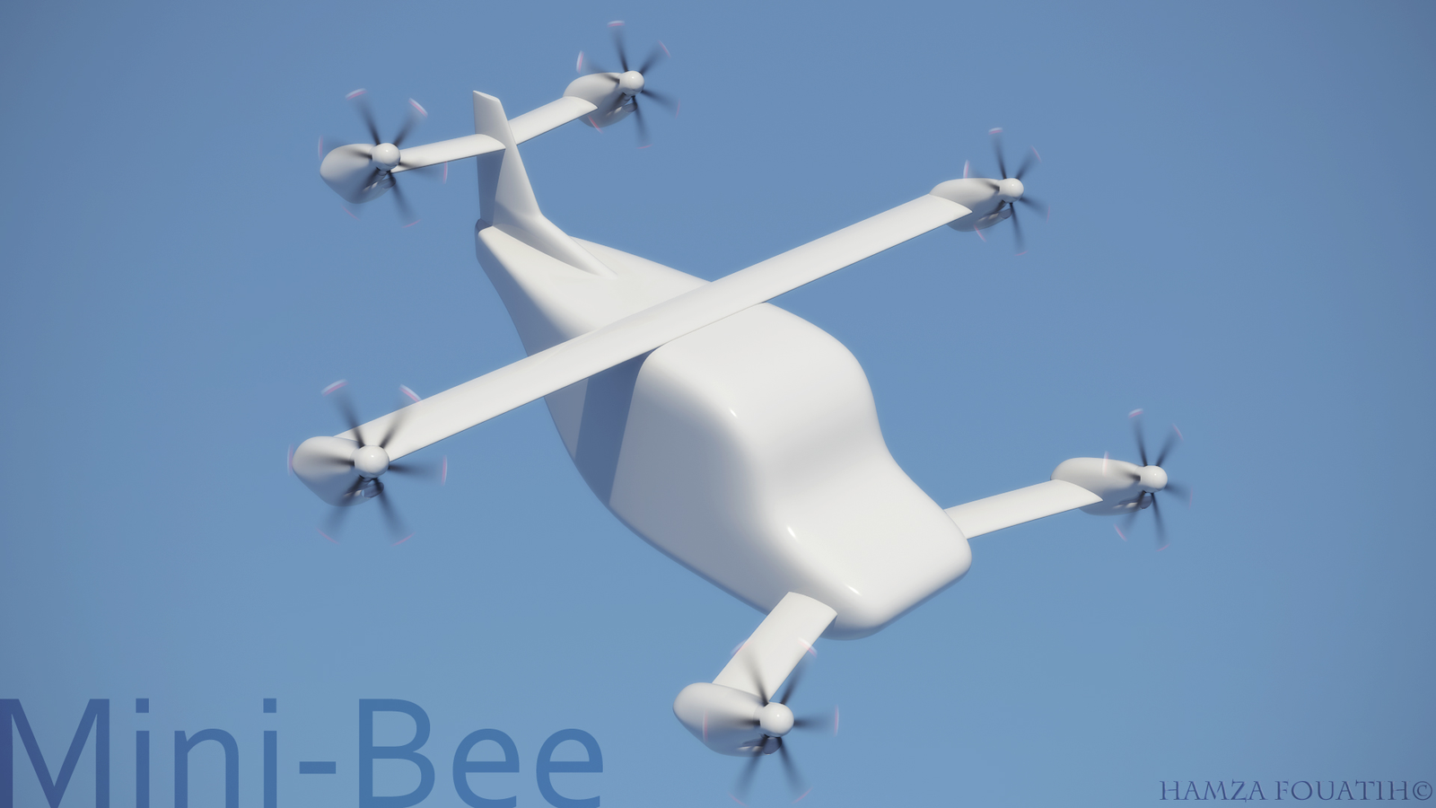
Early digital concept
First communication-style view of the Mini-Bee idea.
|
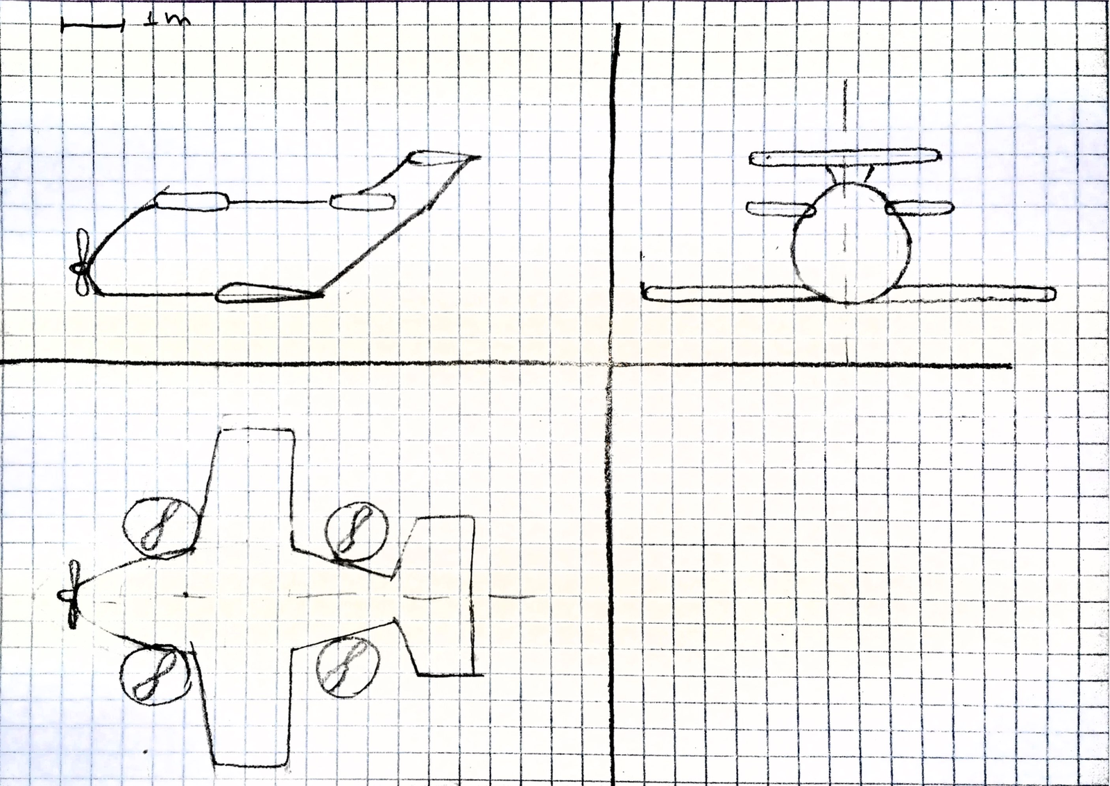
Initial sketch sheet
First aircraft layout intuition with early views.
|
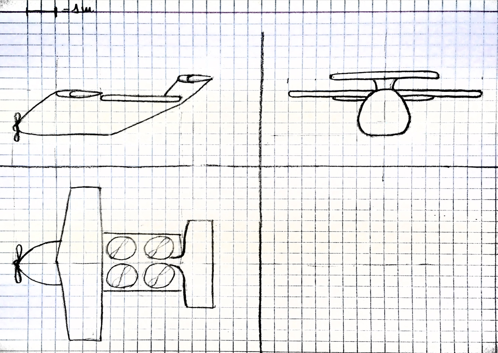
Alternative configuration
Early exploration of another possible aircraft layout.
|


Project overview
The Mini-Bee concept started from a simple operational question: could a compact aircraft combine vertical take-off capability, practical mobility, hybrid propulsion and useful mission applications?
At this early stage, the project was not yet a validated technical architecture. It was an exploration phase.
The objective was to study whether an aircraft could combine some of the operational flexibility of a helicopter with a simpler, more affordable and more adaptable configuration.
The first studies considered a hybrid aircraft using electric propulsion for VTOL phases and a thermal engine for cruise power or onboard electrical generation. These assumptions were later refined through the following TRL stages.
Concept origin
The early Mini-Bee idea was driven by several mission and design needs:
- provide high mobility without depending only on conventional runways;
- explore a low-cost aircraft concept;
- support practical missions such as air ambulance, rescue, emerging-country mobility and personal transportation;
- combine vertical take-off and landing with cruise flight capability;
- investigate hybrid propulsion;
- reduce the dependency on large battery capacity by using a thermal power source;
- prepare a technical basis for future student projects, design work and demonstrator studies.
Early mission framing
|
Mobility The aircraft concept aimed to operate from many types of locations, not only from conventional runways. |
Low cost The early requirement logic included a strong cost objective to make the aircraft accessible and useful. |
Useful missions The first project logic included rescue missions, air ambulance use cases and low-cost personal transportation. |
Historical early assumptions
| Early assumption | Historical interpretation at TRL 0 |
|---|---|
| Hybrid configuration | Electric motors would support VTOL phases, while a thermal engine would provide cruise power and/or electrical generation. |
| VTOL capability | Vertical take-off and landing were identified as a key differentiator for high mobility. |
| Cruise speed | Early objectives mentioned a high cruise speed target around 300 ± 50 km/h. |
| Range | Early objectives mentioned an autonomy target between 600 and 800 km. |
| Mass and capacity | Early studies considered a larger aircraft concept, including 4 or 5 seats and an MTOW around 1550 kg. |
| Cost target | Early requirements mentioned a low-cost objective below 100,000 €. |
Historical note: these assumptions belong to the pre-TRL concept phase. They are not the current Mini-Bee configuration.
First hand sketches
The first hand sketches helped define the initial visual intuition of the aircraft.
They explored early aircraft proportions, basic configuration logic and possible layout directions. At this stage, the aim was not to freeze the design, but to make the concept visible enough to start technical discussions.

Initial sketch sheet – first layout intuition

Alternative early configuration
Early digital concept
The early digital concept was used as a communication visual. It helped present the Mini-Bee idea as a possible hybrid VTOL aircraft before the project reached a mature architecture.
Preliminary technical studies
TRL 0 included early analytical work to check whether the first aircraft intuition could become a credible project direction.
The purpose was not to validate a final design. The purpose was to identify the first technical constraints: lift, mass, power, propulsion, autonomy and operational use.
|
Wing sizing intuition An initial wing chord evaluation explored the relationship between wingspan, stall speed, lift and wing chord. |
Thermal engine search A first engine study examined the possible role of a thermal engine in a hybrid aircraft power architecture. |
Electric propulsion screening Early electric motor comparisons helped identify the challenge of VTOL power-to-weight ratio. |
Wing chord evaluation
The initial wing evaluation used a simple aerodynamic approach to estimate the chord needed for different stall speed assumptions.
This work helped transform the early visual idea into a first sizing discussion. The objective was to connect the aircraft mass assumption, the desired stall speed and the first wing geometry hypotheses.
| Study point | TRL 0 purpose |
|---|---|
| Wing area | Estimate the first order wing surface required to support the aircraft during conventional flight. |
| Stall speed | Compare different stall speed assumptions and their impact on wing chord. |
| Aircraft mass | Understand how the early MTOW assumption influenced the required lift surface. |
| Design consequence | Identify whether the initial aircraft intuition remained compatible with practical wing dimensions. |
Propulsion evaluation
The early propulsion work explored two complementary questions.
First, the thermal engine could potentially support cruise power or electrical generation. Second, the electric motors had to be assessed against the demanding power-to-weight requirements of VTOL flight.
| Propulsion topic | Early interpretation |
|---|---|
| Thermal engine | Considered as a possible power source for cruise flight or onboard electrical generation. |
| Electric motors | Studied for VTOL phases, where high instantaneous power and low mass are critical. |
| Hybrid chain | Explored as a way to reduce dependency on large batteries while preserving vertical take-off capability. |
| Main challenge | Balance mass, power, autonomy, thermal generation and aircraft complexity. |
Early requirement logic
The early requirement work helped structure the first mission needs and technical constraints.
It grouped the first expectations related to speed, range, cost, capacity and aircraft usability.
| Requirement area | TRL 0 interpretation |
|---|---|
| Mission | Explore a useful aircraft concept for rescue, ambulance, mobility and personal transport applications. |
| Architecture | Investigate a hybrid VTOL aircraft combining electric lift and a thermal energy source. |
| Mobility | Reduce dependency on conventional airport infrastructure. |
| Cost | Keep the concept compatible with a low-cost design ambition. |
| Technical maturity | Prepare the transition toward structured TRL 1 work. |
What TRL 0 covered
|
Covered at TRL 0
|
Not yet covered at TRL 0
|
TRL 0 development logic
The TRL 0 phase created the project foundation before entering the formal TRL logic.
| 1. Imagine | 2. Sketch | 3. Frame | 4. Screen | 5. Prepare TRL 1 |
| Mission intuition | Hand sketches and early visuals | Needs and constraints | First technical evaluations | Basic principles observed |
Why TRL 0 mattered
TRL 0 mattered because it captured the first project intuition before any formal technical maturity could be claimed.
It helped transform an idea into a project direction: a hybrid aircraft with VTOL capability, useful missions, high mobility and a need for technical validation.
This stage prepared the transition toward TRL 1, where the first basic principles of the Mini-Bee concept could be identified and documented.
Source documents
| Document | Use in TRL 0 page |
|---|---|
| File:MiniBee HandScketch.pdf | First hand sketches and early visual layout studies. |
| File:Initial Evaluation of MiniBee.pdf | Initial wing chord evaluation and first sizing assumptions. |
| File:Engine Repport.pdf | Thermal engine and electric motor screening. |
| File:BeePlane Info v1.1.pdf | Early mission statement, requirements, diagrams and project framing. |
Image files used on this page
| Wiki file name | Use in page | Link |
|---|---|---|
| mb_trl0_early_3d_render.png | Hero image, visual archive and early digital concept | Open image |
| mb_trl0_hand_sketch_01.png | Visual archive and hand sketch gallery | Open image |
| mb_trl0_hand_sketch_02.png | Visual archive and hand sketch gallery | Open image |
Transition to the next stage
Next maturity step: TRL 1 – Basic Principles Observed.
At TRL 1, the project moves from early intuition and exploratory material toward the identification of basic principles that justify a structured concept phase.