Difference between revisions of "Exercise Arduino FCU English"
Wiki.admin (talk | contribs) |
Wiki.admin (talk | contribs) |
||
| Line 1: | Line 1: | ||
<i>Cette page est disponible en français sur le lien suivant : https://wiki.collaborativebee.com//index.php?title=Exercice_Arduino_FCU</i> | <i>Cette page est disponible en français sur le lien suivant : https://wiki.collaborativebee.com//index.php?title=Exercice_Arduino_FCU</i> | ||
| + | |||
| + | [[fr:Exercice Arduino FCU]] | ||
| + | |||
| + | |||
You will find on this page all informations, exercises and files you need to get started for making a FCU (Flight Control Unit) prototype during your lab work in class. | You will find on this page all informations, exercises and files you need to get started for making a FCU (Flight Control Unit) prototype during your lab work in class. | ||
Revision as of 12:12, 29 September 2023
Cette page est disponible en français sur le lien suivant : https://wiki.collaborativebee.com//index.php?title=Exercice_Arduino_FCU
You will find on this page all informations, exercises and files you need to get started for making a FCU (Flight Control Unit) prototype during your lab work in class.
Some useful Arduino functions
Void setup() : mandatory at the beginning of the program, this corresponds to the initialization of the program (indicate the pins, outputs, inputs)
Void loop() : mandatory in a program, this corresponds to the part of the program that will repeat in a loop.
DigitalRead() / AnalogRead() : allows to read the state (HIGH or LOW) of a digital/analog port of the Arduino board.
DigitalWrite() / AnalogWrite() : allows to write and thus give a state (HIGH or LOW) to a digital/analog port of the Arduino board.
PinMode() : allows to initialize a pin and put it in input or output mode (ex: pinMode(1, OUTPUT)) Delay() : Makes a pause in the program (in ms).
Use this link for any other information or other Arduino functions: https://www.arduino.cc/reference/fr/
Here are some sites that allow you to find all the necessary components for the assembly:
https://www.gotronic.fr/rechercher.htm
https://boutique.semageek.com/fr/2-arduino
Exercise 1 : Get ready - Control of a LED
This exercise is split in 3 objectives : turn on a LED, make it blink and finally control its brightness
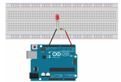
During all this exercise, we will use the assembly below.
Necessary material
- 1 Arduino board
- 1 LED
- 1 220 ohm resistor
- 1 test board
- 2 male/male wires
Assembly realisation
• Connect the digital pin (digital side) number 1 of the Arduino board to the resistor's pin.
• Connect the second pin of the resistor to the anode (positive, longer leg) of the LED.
• Connect the cathode (negative, shorter leg) of the LED to the GND of the Arduino.
Step 1 : Turn on a LED
To switch on this LED, you will need the following Arduino code.
void setup()
{
 pinMode(1, OUTPUT); 	//Initialize digital pin number 1 of the Arduino board in output mode
}
void loop()
{
 digitalWrite(1, HIGH); 	//The current is sent to pin 1, the LED lights up
}
Step 2 : Make an LED blink
This Arduino code allows you to blink a LED at a given frequency.
void setup()
{
 pinMode(1, OUTPUT); //Initialisation de la broche 1 en sortie
}

void loop()
{
 digitalWrite(1, HIGH); //Setting the level to High (Turning on) the LED
 delay(1000);		//Délai de 1000ms dans cette position (LED allumée)
 digitalWrite(1, LOW);	//Delay of 1000ms in this position (LED turned on)
 delay(1000);	//Delay of 1000ms in this position (LED turned off)
}
You can find an explanatory video by following this link : https://www.youtube.com/watch?v=OOR3dfWH8HE
Step 3 : Control the brightness of a LED
Here, the code will vary the light intensity of the LED in such a way that the intensity increases linearly, and when the LED reaches its maximum value (value 255, value HIGH), and then the light intensity decreases until the LED is off (value 0, LOW).
int LED = 3;	 // Definition of the pins and variables used.
int x;		 // Duty cycle

void setup()
{
 pinMode(LED, OUTPUT);
}

void loop()
{
 x = 0;
 while (x <= 255) // Gradually turning on the LED (0 --> 255)
 {
  analogWrite(LED, x);
  delay(10);
  x = x+1;
 }
 x = 255;
 while (x >= 0) // Gradually turning off the LED (0 --> 255)
 {
  analogWrite(LED, x);
  delay(10);
  x = x-1;
 }
}
Exercise 2 : Using a gyroscope
The implementation of a gyroscope using Arduino allows for the determination of the inclinations of a moving device.
Necessary material
- 1 Arduino board
- 1 gyroscope
- 4 male/female wires
Assembly
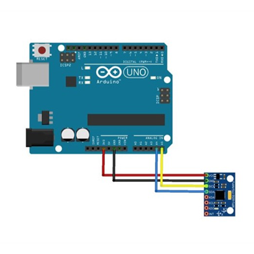
• Connect the GND and VCC terminals respectively to the GND and +5V terminals of the Arduino board
• Connect the SCL terminal of the gyroscope to the A4 analog terminal
• Connect the SDA terminal of the gyroscope to the A5 analog terminal.
Here, the SCL and SDA terminals correspond to the x and y axes of the gyroscope.
NOTE: LEDs can be used on a breadboard as done for the joystick to see the effects of the gyroscope on the LEDs.
Arduino code
#include <Wire.h>
#include "I2Cdev.h"
#include "MPU6050_6Axis_MotionApps20.h"
#if I2CDEV_IMPLEMENTATION == I2CDEV_ARDUINO_WIRE
#include "Wire.h"
#endif
MPU6050 mpu;
#define OUTPUT_READABLE_YAWPITCHROLL
#define LED_PIN 13 // (Arduino is 13, Teensy is 11, Teensy++ is 6)
bool blinkState = false;

bool dmpReady = false;  // set true if DMP init was successful
uint8_t mpuIntStatus;   // holds actual interrupt status byte from MPU
uint8_t devStatus;      // return status after each device operation (0 = success, !0 = error)
uint16_t packetSize;    // expected DMP packet size (default is 42 bytes)
uint16_t fifoCount;     // count of all bytes currently in FIFO
uint8_t fifoBuffer[64]; // FIFO storage buffer

// orientation/motion vars
Quaternion q;           // [w, x, y, z]         quaternion container
VectorInt16 aa;         // [x, y, z]            accel sensor measurements
VectorInt16 aaReal;     // [x, y, z]            gravity-free accel sensor measurements
VectorInt16 aaWorld;    // [x, y, z]            world-frame accel sensor measurements
VectorFloat gravity;    // [x, y, z]            gravity vector
float euler[3];         // [psi, theta, phi]    Euler angle container
float ypr[3];           // [yaw, pitch, roll]   yaw/pitch/roll container and gravity vector

// packet structure for InvenSense teapot demo
uint8_t teapotPacket[14] = { '$', 0x02, 0,0, 0,0, 0,0, 0,0, 0x00, 0x00, '\r', '\n' };

// ================================================================
// ===               INTERRUPT DETECTION ROUTINE                ===
// ================================================================

volatile bool mpuInterrupt = false;     // indicates whether MPU interrupt pin has gone high
void dmpDataReady() {
   mpuInterrupt = true;
}
// ================================================================
// ===                      LEDS                                ===
// ================================================================

const int led_1 = 13 ;
const int led_2 = 12 ;
const int led_3 = 11 ;
const int led_4 = 10 ;
const int led_5 = 9 ;
const int led_6 = 8 ;
const int led_7 = 7 ;
const int led_8 = 6 ;
const int led_9 = 5 ;

// ================================================================
// ===                      INITIAL SETUP                       ===
// ================================================================

void setup() {
    // LEDS

 pinMode(led_1, OUTPUT);
 pinMode(led_2, OUTPUT);
 pinMode(led_3, OUTPUT);
 pinMode(led_4, OUTPUT);
 pinMode(led_5, OUTPUT);
 pinMode(led_6, OUTPUT);
 pinMode(led_7, OUTPUT);
 pinMode(led_8, OUTPUT);
 pinMode(led_9, OUTPUT);

   // join I2C bus (I2Cdev library doesn't do this automatically)
   #if I2CDEV_IMPLEMENTATION == I2CDEV_ARDUINO_WIRE
       Wire.begin();
       TWBR = 24; // 400kHz I2C clock (200kHz if CPU is 8MHz)
   #elif I2CDEV_IMPLEMENTATION == I2CDEV_BUILTIN_FASTWIRE
       Fastwire::setup(400, true);
   #endif

   Serial.begin(115200);
   while (!Serial); // wait for Leonardo enumeration, others continue immediately

   Serial.println(F("Initializing I2C devices..."));
   mpu.initialize();

   Serial.println(F("Testing device connections..."));
   Serial.println(mpu.testConnection() ? F("MPU6050 connection successful") : F("MPU6050 connection failed"));

   Serial.println(F("\nSend any character to begin DMP programming and demo: "));
   while (Serial.available() && Serial.read()); // empty buffer
   while (!Serial.available());                 // wait for data
   while (Serial.available() && Serial.read()); // empty buffer again

   Serial.println(F("Initializing DMP..."));
   devStatus = mpu.dmpInitialize();

   // supply your own gyro offsets here, scaled for min sensitivity
   mpu.setXGyroOffset(220);
   mpu.setYGyroOffset(76);
   mpu.setZGyroOffset(-85);
   mpu.setZAccelOffset(1788); // 1688 factory default for my test chip

   // make sure it worked (returns 0 if so)
   if (devStatus == 0) {
       // turn on the DMP, now that it's ready
       Serial.println(F("Enabling DMP..."));
       mpu.setDMPEnabled(true);

       // enable Arduino interrupt detection
       Serial.println(F("Enabling interrupt detection (Arduino external interrupt 0)..."));
       attachInterrupt(0, dmpDataReady, RISING);
       mpuIntStatus = mpu.getIntStatus();

       // set our DMP Ready flag so the main loop() function knows it's okay to use it
       Serial.println(F("DMP ready! Waiting for first interrupt..."));
       dmpReady = true;

       // get expected DMP packet size for later comparison
       packetSize = mpu.dmpGetFIFOPacketSize();
   } else {
       // ERROR!
       // 1 = initial memory load failed
       // 2 = DMP configuration updates failed
       // (if it's going to break, usually the code will be 1)
       Serial.print(F("DMP Initialization failed (code "));
       Serial.print(devStatus);
       Serial.println(F(")"));
   }

   // configure LED for output
   pinMode(LED_PIN, OUTPUT);
}
// ================================================================
// ===                    MAIN PROGRAM LOOP                     ===
// ================================================================

void loop() {
   // if programming failed, don't try to do anything
   if (!dmpReady) return;

   // wait for MPU interrupt or extra packet(s) available
   while (!mpuInterrupt && fifoCount < packetSize) {
       // other program behavior stuff here
       // if you are really paranoid you can frequently test in between other
       // stuff to see if mpuInterrupt is true, and if so, "break;" from the
       // while() loop to immediately process the MPU data
   }

   // reset interrupt flag and get INT_STATUS byte
   mpuInterrupt = false;
   mpuIntStatus = mpu.getIntStatus();

   // get current FIFO count
   fifoCount = mpu.getFIFOCount();

   // check for overflow (this should never happen unless our code is too inefficient)
   if ((mpuIntStatus & 0x10) || fifoCount == 1024) {
       // reset so we can continue cleanly
       mpu.resetFIFO();
       Serial.println(F("FIFO overflow!"));

   // otherwise, check for DMP data ready interrupt (this should happen frequently)
   } else if (mpuIntStatus & 0x02) {
       // wait for correct available data length, should be a VERY short wait
       while (fifoCount < packetSize) fifoCount = mpu.getFIFOCount();

       // read a packet from FIFO
       mpu.getFIFOBytes(fifoBuffer, packetSize);

       // track FIFO count here in case there is > 1 packet available
       // (this lets us immediately read more without waiting for an interrupt)
       fifoCount -= packetSize;

       mpu.dmpGetQuaternion(&q, fifoBuffer);
       mpu.dmpGetGravity(&gravity, &q);
       mpu.dmpGetYawPitchRoll(ypr, &q, &gravity);


// BEGINNING OF OUR CODE

// MPU
      int XX ;
      int YY ;
      XX = (ypr[2] * 180/M_PI) * (128/90) ; // entre -128 et 128
      YY = (ypr[1] * 180/M_PI) * (128/90) ;

      // It's p and r that are interesting us

      int puiss_led_11 ;
      int puiss_led_22 ;
      int puiss_led_33 ;
      int puiss_led_44 ;
      int puiss_led_55 ;
      int puiss_led_66 ;
      int puiss_led_77 ;
      int puiss_led_88 ;
      int puiss_led_99 ;

      puiss_led_11 = 100 + (0 * XX) - (1.5 * YY);
      puiss_led_22 = 100 - (0.75 * XX) - (1 * YY);
      puiss_led_33 = 100 + (0.75 * XX) - (1 * YY);
      puiss_led_44 = 100 - (1 * XX) - (0 * YY);
      puiss_led_55 = 100 + (1 * XX) - (0 * YY);
      puiss_led_66 = 100 - (1.25 * XX) + (1 * YY);
      puiss_led_77 = 100 - (0.75 * XX) + (1 * YY);
      puiss_led_88 = 100 + (0.75 * XX) + (1 * YY);
      puiss_led_99 = 100 + (1.25 * XX) + (1 * YY);

      analogWrite(led_1, puiss_led_11);
      analogWrite(led_2, puiss_led_22);
      analogWrite(led_3, puiss_led_33);
      analogWrite(led_4, puiss_led_44);
      analogWrite(led_5, puiss_led_55);
      analogWrite(led_6, puiss_led_66);
      analogWrite(led_7, puiss_led_77);
      analogWrite(led_8, puiss_led_88);
      analogWrite(led_9, puiss_led_99);

      // Show in the console the differents brightenesses of the LED
      Serial.print("XX = ");
      Serial.print(XX);
      Serial.print("YY = ");
      Serial.print(YY);
      Serial.print("\tPuiss 1 = ");
      Serial.print(puiss_led_11);
      Serial.print("\tPuiss 2 = ");
      Serial.print(puiss_led_22);
      Serial.print("\tPuiss 3 = ");
      Serial.print(puiss_led_33);
      Serial.print("\tPuiss 4 = ");
      Serial.print(puiss_led_44);
      Serial.print("\tPuiss 5 = ");
      Serial.print(puiss_led_55);
      Serial.print("\tPuiss 6 = ");
      Serial.print(puiss_led_66);
      Serial.print("\tPuiss 7 = ");
      Serial.print(puiss_led_77);
      Serial.print("\tPuiss 8 = ");
      Serial.print(puiss_led_88);
      Serial.print("\tPuiss 9 = ");
      Serial.println(puiss_led_99);

// END OF OUR CODE

     // blink LED to indicate activity
     blinkState = !blinkState;
     digitalWrite(LED_PIN, blinkState);
   }
}
Exercise 3A : Using a joystick
Implementing a joystick on an Arduino allows for real-time retrieval of information about the Joystick's position. In this case, LEDs are used in the setup to provide a visual effect. However, these LEDs are not necessary for this package.
Necessary material
- 1 Arduino board
- 1 Joystick
- 4 LEDs
- At least 4 220 ohms resistors
- 1 breadboard
- 5 male/female wires
- 8 male/male wires
Assembly
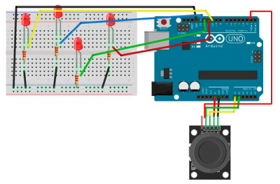
• Connect the 4 LEDs with the resistors on the breadboard to the digital pins (e.g. 10, 11, 12, 13) on the Arduino board. Arrange them in a diamond shape so that one LED corresponds to one direction of the Joystick (left, up, etc.).
• Connect the Joystick to the Arduino board:
• The GND pin of the Joystick should be connected to the GND of the Arduino board
• The Vcc pin of the Joystick should be connected to the +5V of the Arduino board
• The VRx pin of the Joystick should be connected to A0 (analog side) of the Arduino board
• The VRy pin of the Joystick should be connected to A1 (analog side) of the Arduino board
• The SW pin of the Joystick should be connected to pin 2 (digital side) of the Arduino board
In this setup, the LEDs will indicate the orientation of the Joystick. For example, if the Joystick is moved forward, one of the LEDs will light up and the others will be off. The lit LED will represent the front side of the Joystick. The same applies to the other LEDs and the other sides of the Joystick.
For a more precise analysis of the Joystick's position, go to Tools -> Serial Monitor. You will be provided with the exact positions of the Joystick.
NOTE: Additional LEDs can be added to increase the precision of the information. For example, if 4 more LEDs (8 LEDs in total arranged in a circle) are added, it will be possible to determine if the Joystick is in diagonal positions: North-East, North-West, South-East, South-West.
Regarding the joystick, the VRx and VRy pins correspond to the Forward/Backward and Left/Right positions of the Joystick. The SW pin represents a press on the Joystick as it also functions as a push button.
Arduino code
// Arduino pin numbers
const int SW_pin = 2; //The SW pin of the Joystick is connected to digital pin 2 on the Arduino board
const int X_pin = 0; //The X pin of the Joystick is connected to the analog pin A0 on the Arduino board
const int Y_pin = 1; //The Y pin of the Joystick is connected to the analog pin A1 on the Arduino board

#define UP_LED 10
#define RIGHT_LED 11	//Define the pins for the LEDs
#define LEFT_LED 12
#define DOWN_LED 13

void setup() {
 pinMode(SW_pin, INPUT);
 digitalWrite(SW_pin, HIGH);
 Serial.begin(115200);

 pinMode(UP_LED, OUTPUT);
 pinMode(RIGHT_LED, OUTPUT); // The 4 LEDs are defined as outputs in the code
 pinMode(LEFT_LED, OUTPUT);
 pinMode(DOWN_LED, OUTPUT);
}

void loop() {
 Serial.print("Switch:  "); //Displaying the values in the serial monitor
 Serial.print(digitalRead(SW_pin));
 Serial.print("\n");
 Serial.print("X-axis: ");
 Serial.print(analogRead(X_pin));
 Serial.print("\n");
 Serial.print("Y-axis: ");
 Serial.println(analogRead(Y_pin));
 Serial.print("\n\n");

 delay(500);

 if(analogRead(X_pin) == 1023){ 	//If the joystick is forward, then the
   digitalWrite(UP_LED, HIGH); 	// LED UP is turned on.

} else if(analogRead(X_pin) == 0){ 		//If the joystick is backward, then the
   digitalWrite(DOWN_LED, HIGH); 		// LED DOWN is turned on
}
else if(analogRead(Y_pin) == 1023){	 // If the joystick is on left, then the
   digitalWrite(RIGHT_LED, HIGH); 		// LED RIGHT is turned on
}
else if(analogRead(Y_pin) == 0){ 		//If the joystick is on right, then the
   digitalWrite(LEFT_LED, HIGH);  	        // LED LEFT is turned on
}

else if(digitalRead(SW_pin) == 0){ 		//If the joystick is pressed
 digitalWrite(UP_LED, HIGH); 		        //then all the LEDs are turned on
 digitalWrite(LEFT_LED, HIGH);
 digitalWrite(RIGHT_LED, HIGH);
 digitalWrite(DOWN_LED, HIGH);
}

else{				//If there is no pressure on the joystick,
 digitalWrite(UP_LED, LOW); 	//then all the LEDs turn off
 digitalWrite(LEFT_LED, LOW);
 digitalWrite(RIGHT_LED, LOW);
 digitalWrite(DOWN_LED, LOW);
}
}
Exercise 3B : Using a joystick to determine the position (pressed or not) of it (simplified version)
The implementation of a Joystick using Arduino allows for real-time retrieval of information on the Joystick's position. Here, LEDs are used in the setup to provide a visual effect, however, these LEDs are not essential in this package.
The goal is to use only 4 LEDs and adjust the brightness of each LED based on the Joystick's position. The brightness of the LEDs will increase proportionally to the Joystick's position.
EXAMPLE: if the Joystick is slightly tilted to the right, then the right LED will flicker with a low intensity and as the Joystick tilts further to the right, the right LED will have an increasingly bright light intensity until it reaches its maximum (when the joystick is pressed down).
Necessary material
- 1 Arduino board
- 1 joystick
- 4 LEDs
- At least 4 220 ohm resistors
- A breadboard
- 4 male-to-female wires
- 12 male-to-male wires
Assembly
• Connect the 8 LEDs with the resistors on the breadboard to the digital pins (e.g. 10, 11, 12, 13) on the Arduino board. Arrange them in a diamond shape (2 in each direction) so that one LED corresponds to one direction of the Joystick (left, up, etc.).
• Connect the Joystick to the Arduino board:
o The GND pin of the Joystick should be connected to the GND of the Arduino board
o The Vcc pin of the Joystick should be connected to the +5V of the Arduino board
o The VRx pin of the Joystick should be connected to A0 (analog side) of the Arduino board
o The VRy pin of the Joystick should be connected to A1 (analog side) of the Arduino board
o The SW pin of the Joystick should be connected to pin 2 (digital side) of the Arduino board
NOTE: For a more accurate analysis of the Joystick's position, go to Tools -> Serial Monitor. You will receive the exact positions of the Joystick.
Arduino code
int axey = A1;   // Reference input for the Y axis.
int axex = A0;   // Reference input for the X axis.
int ledD = 12;   // Lower LED. This value should be adjusted to suit your circuit!
int ledup = 9;    // Upper LED. This value should be adjusted to suit your circuit!
int ledL = 13;    // Left LED. This value should be adjusted to suit your circuit!
int ledR = 7;    //  Right LED. This value should be adjusted to suit your circuit!
int valeurX;
int valeurY;

void setup() {
 Serial.begin(9600);	// Defining the LEDs as outputs.
 pinMode(ledup, OUTPUT);
 pinMode(ledD, OUTPUT);
 pinMode(ledL, OUTPUT);
 pinMode(ledR, OUTPUT);
}

void loop() {
 valeurX = analogRead(axex);
 if (valeurX > 512){ // droite
  analogWrite(ledR,(valeurX-513)/2); 		// This formula allows for the progressive increase of light intensity for values between 513 and 1023.
  Serial.print("x = ");
  Serial.println(valeurX);
 }
 else
 {
  digitalWrite(ledR, LOW );
 }

 valeurX = analogRead(axex);
 if (valeurX < 511){ // gauche
  analogWrite(ledL,(-valeurX+510)/2);		// This formula allows for the progressive increase of light intensity for values between 0 and 510.
  Serial.print("x = ");
  Serial.println(valeurX);
 }
 else
 {
  digitalWrite(ledL, LOW );
 }

 valeurY = analogRead(axey);
 if (valeurY > 512){ // bas
  analogWrite(ledD, (valeurY-513)/2); 		// This formula allows for the progressive increase of light intensity for values between 513 and 1023.
  Serial.print("y = ");
  Serial.println(valeurY);
 }
 else
 {
  digitalWrite(ledD, LOW );
 }

valeurY = analogRead(axey);
if (valeurY < 511){ // haut
 analogWrite(ledup,(-valeurX+510)/2);	// This formula allows for the progressive increase of light intensity for values between 0 and 510.
 Serial.print("y = ");
 Serial.println(valeurY);
 }
 else
 {
  digitalWrite(ledup, LOW );
 }
}
Exercise 3C : Using a joystick to determine the position (pressed or not) of it (complete version)
The implementation of a joystick using Arduino allows for real-time information retrieval on its position. Here, LEDs are used in the circuit to achieve a visual effect. However, these LEDs are not essential in this package.
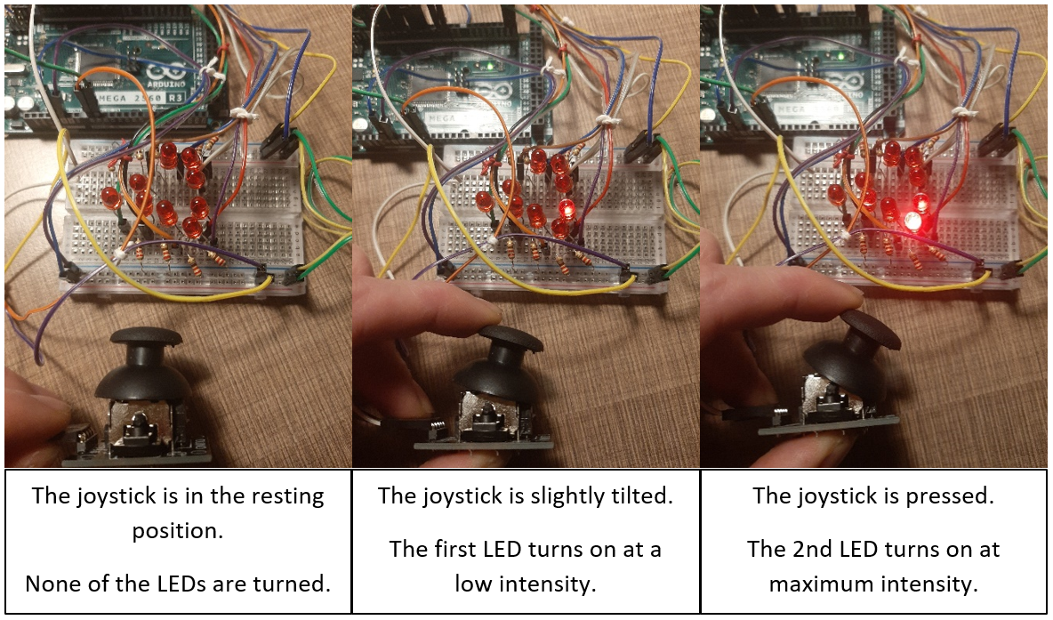
The objective is that when the joystick is tilted 50% in one direction (e.g. left), one LED is turned on at 50% of its maximum intensity. Then when the joystick is in the maximum left position, a second LED is turned on at maximum intensity.
Necessary material
- 1 Arduino board
- 1 joystick
- 8 LEDs
- At least 8 220 ohms resistors
- 1 breadboard
- 4 male/female wires
- 12 male/male wires
Assembly
• Connect the 8 LEDs with the resistors on the breadboard to the digital pins (e.g. 10, 11, 12, 13) on the Arduino board. Arrange them in a diamond shape (2 in each direction) so that one LED corresponds to one direction of the Joystick (left, up, etc.).
• Connect the Joystick to the Arduino board:
o The GND pin of the Joystick should be connected to the GND of the Arduino board
o The Vcc pin of the Joystick should be connected to the +5V of the Arduino board
o The VRx pin of the Joystick should be connected to A0 (analog side) of the Arduino board
o The VRy pin of the Joystick should be connected to A1 (analog side) of the Arduino board
o The SW pin of the Joystick should be connected to pin 2 (digital side) of the Arduino board
• Remember: Each LED needs a 220 ohms resistor in series to protect the circuit. Connect the cathode of each LED (the shorter segment) to ground and the anode (the longer segment) to a digital output pin.
• The Joystick acts as 2 potentiometers: Its horizontal position is given by a number from 0 (left) to 1023 (right). Same thing in vertical (average value 512)
• Add conditions in the code. (See code below).
EXAMPLE: If the value of the Joystick is less than a given value (e.g. 300, Joystick slightly tilted) then the 1st LED lights up (low intensity, see LED slide), then if the value is minimal (0, Joystick pressed) then the 2nd LED lights up (maximum intensity).
NOTE: The setup matches the one above, but with the addition of 4 LEDs, one added to each end (top, bottom, left, right).
Illustration
Arduino code
int axey = A1;   	// Reference input for Y axis
int axex = A0;	   // Reference input for X axis
int ledup = 12; 	  // LED lower . This value should be adjusted to your setup!
int ledupup = 10;  // LED Lower ++. This value should be adjusted to your setup!
int ledD = 9; 	   // LED upper				“”
int ledDD = 5;   	// LED upper ++.			“”
int ledL = 13;  	  // LED left.				“”
int ledLL = 11;  	  // LED left  ++.			“”
int ledR = 7;    	// LED right				“”
int ledRR = 8;   	// LED right ++.			“”
int valeurX;
int valeurY;

void setup() {
 Serial.begin(9600);	// Defining the LEDs as outputs
 pinMode(ledup, OUTPUT);
 pinMode(ledupup, OUTPUT);
 pinMode(ledD, OUTPUT);
 pinMode(ledDD, OUTPUT);
 pinMode(ledL, OUTPUT);
 pinMode(ledLL, OUTPUT);
 pinMode(ledR, OUTPUT);
 pinMode(ledRR, OUTPUT);
}

void loop() {
 valeurX = analogRead(axex);
 if (valeurX > 700){ 		// Right
  analogWrite(ledR,50);	// The right LED is turned on with an intensity of 50 out of 255
  Serial.print("x = ");
  Serial.println(valeurX);
 }
 else{
   digitalWrite(ledR, LOW );
 }

 valeurX = analogRead(axex);
 if (valeurX > 1022){ 		// Right ++, turned on when the joystick is in max position
  digitalWrite(ledRR, HIGH);	// The LED on the far right is turned on at maximum intensity.
  Serial.print("x = ");
  Serial.println(valeurX);
 else{
  digitalWrite(ledRR, LOW );
 }

 valeurX = analogRead(axex);
 if (valeurX < 400){ 		// Left
  analogWrite(ledL,50);
  Serial.print("x = ");
  Serial.println(valeurX);
 }
 else
 {
  digitalWrite(ledL, LOW );
 }

 valeurX = analogRead(axex);
 if (valeurX < 1){  		// Left ++
  digitalWrite(ledLL, HIGH);
  Serial.print("x = ");
  Serial.println(valeurX);
 }else
 {
  digitalWrite(ledLL, LOW );
 }

 valeurY = analogRead(axey);
 if (valeurY > 700){ 		// High
  analogWrite(ledup,50);
  Serial.print("y = ");
  Serial.println(valeurY);
 }else
 {
  digitalWrite(ledup, LOW );
 }
 valeurY = analogRead(axey);
 if (valeurY > 1022){  		// High ++
  digitalWrite(ledupup, HIGH);
  Serial.print("y = ");
  Serial.println(valeurY);
 }else
 {
  digitalWrite(ledupup, LOW );
 }

valeurY = analogRead(axey);
 if (valeurY < 400){		 // Down
  analogWrite(ledD,50);
  Serial.print("y = ");
  Serial.println(valeurY);
 }else
 {
  digitalWrite(ledD, LOW );
 }

 valeurY = analogRead(axey);
 if (valeurY < 2){ 		// Down ++
  digitalWrite(ledDD, HIGH);
  Serial.print("y = ");
  Serial.println(valeurY);
 }else
 {
  digitalWrite(ledDD, LOW );
 }
}
NOTE: To obtain the precise position of the Joystick on the x and y axis, go to the Tools menu -> Serial Monitor, the values will scroll in real time.


